
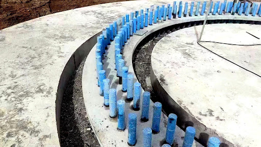
Wind turbine foundations are designed to transfer large static and cyclic loads, but the reliability of the installation often depends on a very narrow interface: the grout layer between the steel tower base, anchor components and concrete foundation. When this layer is placed correctly, it fills construction tolerances and helps maintain stable load transfer. When it is placed poorly, problems such as voids, leakage, segregation, early vibration damage or thermal cracking can appear before the turbine is even commissioned.
For contractors, the practical question is not simply which grout has the highest compressive strength. The more important question is whether the material can be selected, mixed, placed and cured in a way that fits the project temperature, gap thickness, installation window and exposure conditions. The following field guide summarizes a construction workflow and a cracking case review for high-strength non-shrink grout used in wind turbine foundations.
Table of Contents
1. Select grout by strength, flow and field conditions
Wind turbine foundation grout is commonly used for onshore and offshore foundation installation, anchor-bolt zones, fatigue-sensitive equipment support and high-demand gap filling. In one representative product classification, wind power grout grades cover 28-day strength levels from 80 MPa to 140 MPa, with an offshore grade at 125 MPa. The same technical guidance also emphasizes a typical initial flow target of at least 300 mm and a 30-minute retained flow target of at least 260 mm, subject to project adjustment.
| Grade | 1-day strength | 3-day strength | 28-day strength | Typical flow target |
| CBGM-80 | >=20 MPa | >=50 MPa | >=80 MPa | Initial >=300 mm; 30 min >=260 mm |
| CBGM-100 | >=30 MPa | >=60 MPa | >=100 MPa | Same target; adjustable by project |
| CBGM-110 | >=40 MPa | >=65 MPa | >=110 MPa | Same target; adjustable by project |
| CBGM-120 | >=40 MPa | >=70 MPa | >=120 MPa | Same target; adjustable by project |
| CBGM-130 | >=45 MPa | >=75 MPa | >=130 MPa | Same target; adjustable by project |
| CBGM-140 | >=45 MPa | >=80 MPa | >=140 MPa | Same target; adjustable by project |
| CBGM-125 offshore | >=40 MPa | >=70 MPa | >=125 MPa | Offshore wind foundation use |
Table 1. Representative wind power grout classes. Final selection should follow the project specification, temperature and installation conditions.
Strength alone is not enough. Wind turbine grouting often involves tight spaces, complex contact areas and large annular zones. Flowability, anti-segregation behavior, non-shrink performance and curing control all affect whether the grout actually supports the designed interface. If steel-fiber grout is used, fibers should be dispersed gradually after the powder and water have been mixed, until the fibers are uniformly distributed in the grout.
2. Follow a controlled field workflow

Figure 2. A practical wind turbine grouting workflow: clean and pre-wet, mix with controlled water, place continuously from one side, then protect curing.
Most wind foundation grout defects are related to site variables rather than the specified strength grade. A clear workflow should be agreed before work begins.
Prepare the substrate and formwork. Remove dust, laitance, loose particles, oil and standing water. The formwork must be rigid and sealed at the bottom to prevent leakage.
Pre-wet correctly. For absorbent concrete, pre-wet the surface in advance and remove free water before grouting. In hot weather, adjust the timing so the surface is damp but not covered by standing water.
Use controlled water dosage. Follow the manufacturer-recommended water amount. Do not add extra water to improve apparent flow, because excess water can increase segregation, reduce strength and create dimensional instability.
Mix close to the workface. Small placements may use a handheld mixer; large placements should use suitable larger equipment. Avoid long-distance transport or vibration of mixed grout.
Place continuously from one side. For secondary grouting, pour from one side until material flows out from the opposite side. Do not vibrate the grout layer. If a grout pusher is used, move the material along the lower flow direction rather than disturbing the middle or upper layer.
Protect early curing. Cover the surface immediately. After hardening and temperature reduction, continue moist curing. Avoid vibration or loading during early hardening, and remove formwork only after the specified curing period.
3. Understand why cracking can occur
A visible crack is sometimes treated as a material-quality problem, but in cement-based grout it may also be a thermal-management problem. High-strength grout develops hydration heat during early hardening. If the formwork is removed too early or the hot grout surface is exposed to very cold curing water, the outside of the grout can cool much faster than the interior. This creates tensile stress and may lead to thermal cracking.
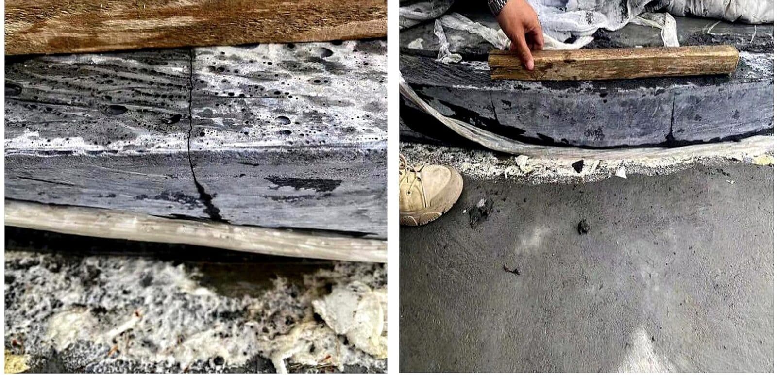
Figure 3. Thermal cracking case: large temperature differences during early curing can create visible cracks in the grout layer.
In a cold-region wind project, a CBGM-120 wind power grout developed serious cracking after placement, with average crack spacing of approximately 20-30 cm. The field review found a large day-night temperature difference. After demolding, the grout still retained hydration heat of approximately 40-50°C, while cold water from melted snow below 10°C was used for curing. The sudden cooling produced a large internal-external temperature difference and caused thermal cracks.
The corrective action was straightforward: strengthen insulation, cover the grout with multiple layers of insulating material, avoid cold-water curing during the hydration-heat peak and extend the demolding time. After these measures were adopted, the cracking condition improved significantly.
4. Use a practical cracking checklist
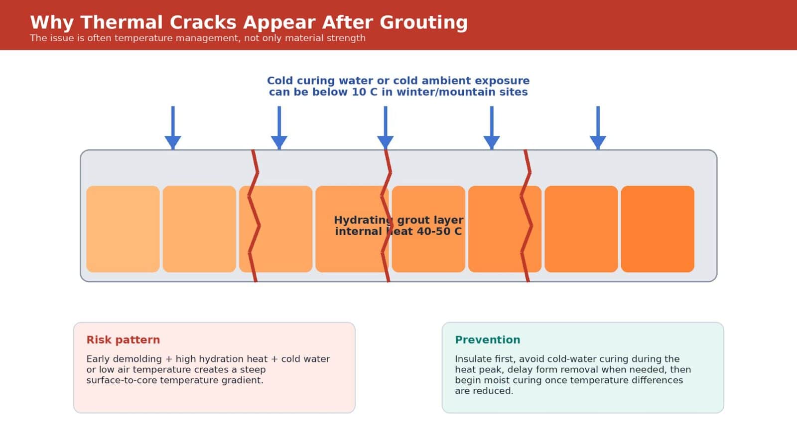
Figure 4. Thermal cracking mechanism: hot internal grout plus sudden surface cooling can create tensile stress.
When cracking is observed after wind turbine foundation grouting, the first response should be diagnosis rather than guesswork. A practical checklist includes the following questions:
- Was the water dosage within the recommended range? Excess water can cause bleeding, segregation and later shrinkage-related symptoms.
- Was the grout used within the permitted working time after water was added?
- Was formwork removed too early? In many projects, formwork removal should be delayed until the grout has reached sufficient early stability.
- Was there vibration or loading during the first day after placement?
- Was the grout exposed to a large temperature difference after demolding?
- Was cold water applied while hydration heat remained high?
- Was moist curing continued after the grout temperature approached ambient conditions?
- Was the surface protected from wind, direct sunlight, freezing conditions or rapid drying?

Figure 5. Crack diagnosis should consider water dosage, demolding time, vibration, temperature difference and curing practice.
5. Special attention for winter and temperature-sensitive work
In winter construction, exposed grout should be covered promptly with plastic film and insulation materials such as geotextile, straw mats or cotton quilts. If there is no special strength-growth requirement, the initial curing temperature should not be below 5°C. Under negative temperature conditions, water curing should be avoided. If the surface temperature of the grout after demolding differs from the ambient temperature by more than 20°C, insulation should be used to slow the temperature change.
In hot weather, the opposite risk is rapid surface moisture loss. Work should be scheduled in the morning or evening where possible, and the surface should be covered immediately after placement. Whether the project is in a desert, plateau, coastal or winter environment, the objective is the same: keep temperature and moisture changes gradual during the early hardening period.
Conclusion
Wind turbine foundation grout is a small layer with a large structural responsibility. It must transfer load, fill construction tolerances, resist vibration and remain dimensionally stable during service. A successful installation depends on more than a high compressive-strength number. It requires proper grade selection, controlled water dosage, clean substrates, continuous one-side placement, protected curing and careful thermal management.
For technical resources on wind turbine foundation grouting materials, visit Sino-sina Building Materials Co., Ltd. at zrete.com.
Author Bio
Sino-sina Building Materials Co., Ltd. provides technical materials for concrete infrastructure, wind power installation, structural repair and durability protection. The company focuses on high-strength non-shrink grout, UHPC, concrete repair systems, protective coatings and related construction materials for onshore and offshore applications. Website: https://www.zrete.com


