Table of Contents
Introduction:
Bitumen is usually placed surfaces as a binding substance and is directly visible towards the warmth of the sunlight. Therefore, they are to be analyzed for this before its functions.
These are used to ascertain the tendency to stretch, the elasticity, like other physical properties of the sample. It help in selecting the bitumen type based on atmospheric conditions and other reliable features while its application in construction to have a safe structure.
Related theory:
These two elements are defined to examine the highest temperature when sample starts to take the spark.
Flash point:
The heat when the substance gives a spark for the reason that volatile vapours are generated is characterized with flash point.
Fire point:
The temperature at which the vapors trap fire for span of minimum 5 seconds is designated to be fire point.
Both these variate depending upon the grade and sort of bitumen. It contains some hydrocarbons which upon heating releases certain volatile materials which catch fire easily proving it to be hazardous.
It is used as an aggregate binder in pavement design. The temperatures on field should be maintained based on these two points majorly to avoid critical situations.
The flash point can be determined by both open cup and closed cup tester method whereas the fire point can only be determined by open cup tester. The following two apparatuses whose various components and procedure are described below are as follows:
1)Pensky martens tester:
It has further two methods to determine these:
- Open cup tester
- Close cup tester
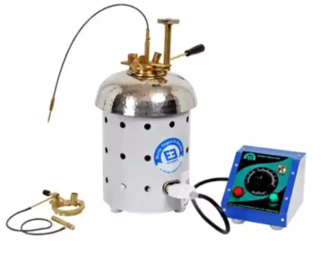
Figure 1 penky martens apparatus
2)Cleveland cup apparatus.
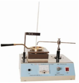
Figure 2 Cleveland Cup Apparatus
Apparatus and materials:
The apparatus are as follows:
- Tester with closed cup which is created of brass and outside is elongated on top of the flange. Its flange may accommodate its lid as well as the cup fire with handle to accurately assemble it. Width of rim is 12mm and thickness is 3mm.
- Testers with Open cup cover is exchanged with clip on its rim by calibration of thermometer along with proper set up.
- Cleveland cup consists of heating plate, test cup spark applicator, temperature determining device, and heating plate support along with proper stand.
- A stirrer used to make up a uniform temperature through out the sample created with brass. Manual rotator is used for cutback bitumen.
- A cover prepared with brass is provided which fits properly on the cup. This concealment is provided with four openings whose area variate i.e. For releasing A it 1604.6 mm2,of B & C is 75% A & D variates based on its height.
- Shutter of brass arranged with lid; such that it circulates on the parallel alignment of the cover in one extreme point and opens it to other.
- Flame applicator including a tip of 0.7 or 0.8mm is used.
- A heating device is used along with a temperature regulator.
- A Thermometer
- Air bath
- Bituminous substance and solvent for cleansing.
Procedure:
The following system is adopted for bituminous substance aside from cutback to define flash point using tester with closed cup:
- Wash all the components through with the solvent and make them dry.
- Heat the mixture up to 100 ̊C till it is converted to liquid state
- Add the mixture up to the filling mark.
- Close it through the cover appropriately.
- Set the cup on fire/heating chamber.
- Add the thermometer and manage the flame recommended as 4mm. The increment is made at an interval of max 6 ̊C/minute.
- The rotator is operated at 60rev/min.
- The standard flame is employed by discontinuing the rotator at 17 ̊C and continue applying it till 104 ̊C with 1 sec interval and after this at a difference of 2 seconds.
- Calibration of a clear flash is determined.
Cutback Bitumen:
- Our solution is set to heat underneath the flash point i.e.17 ̊C. The space in between but the instruments is removed.
- The same method is adopted except the rate of application of heat which is controlled with an increase of 1-1.5 ̊C /minute.
- The rabble rouser is swiveled at 70 to 80rev/min.
- The flame for test is employed, rest stages are adopted as before at a rise of each 0.5 ̊C interval.
Tester with an open cup:
- The same method is adopted only lid is not adopted and is replaced with a clipping object positioned correctly.
- A temperature measuring device is added with the adjustment of changes as per the requirements stated above.
- Top layer is observed carefully.
- The stirrer here is circulated by hand.
- The calibrations are noted down for a different flash and continued with continuous heating for fire point determination.
Cleveland cup apparatus:
The steps adopted are similar as above, the only difference is it is an old method.
Observations:
The following observations are carried out:
| Sr.No | Temperature ( ̊C ) | Flash point ( ̊C ) | Fire point ( ̊C ) |
| 1 | |||
| 2 | |||
| 3 | |||
| 4 | |||
| 5 |
Flash point = arithmetic mean
Fire point = arithmetic mean
Calculations:
A correction factor is usually adopted to balance pressure.
Corrected flash/fire point = C+0.03(760-P)
Where,
C= observed flash/fire point
P= Barometric Pressure (mm of Hg)
Graphs:
A graph is plotted along with time (along x-axis) & temperature(along y-axis).
Comments:
These two determine the max or the critical temperatures for the design considerations in order to avoid hazards.
| Property | AC-2.5 | AC-5 | AC-10 | AC-20 | AC-40 |
| Flash point | 163 | 177 | 219 | 232 | 232 |
AC-10 is majorly adopted.
Precautions:
- A proper care is to be adopted to maintain the heat in the sample.
- Blue flame layer is not assumed to be the fire point.
- The apparatus is thoroughly cleaned by using the solvent and dried.
- Don’t breathe near the apparatus as volatile vapors may prove hazardous.
- Any wave generating machine is to be turned off to obtain a better result.
- Assembly of the apparatus is to be maintained properly.