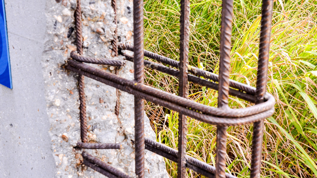
Concrete is an intrinsically strong construction material when it comes to bearing compressive loads and developing compressive stresses against them. However, when the same concrete member is subjected to tensile forces, it is like, hands up, I give in. This might sound hilarious, but this problem of concrete gets magnified in the form of structural cracking, deflections and ultimately collapse when it comes to the level of a structure. We are sure it doesn’t sound funny now, right?
The only option of using concrete in structural works is to reinforce it so it does not crack when subjected to tensile stresses and steel, invariably, is the best reinforcing material for essentially all concrete types.

There are many types of reinforcements that can be used in concrete to serve different purposes, mostly to increase the tensile strength of concrete. We shall discuss all these types in detail so that you get the most out of this read.
Table of Contents
Types of Concrete Reinforcement
The type of concrete reinforcement you use will depend upon the characteristic you are targeting. If reinforcement is to be provided to increase tensile strength, steel bars or mesh reinforcement can be used. Similarly, if post-cracking ductility is required, you can go for providing fiber reinforcement, etc.
The different reinforcement types that can be used in concrete are summarized and elucidated herewith.
-
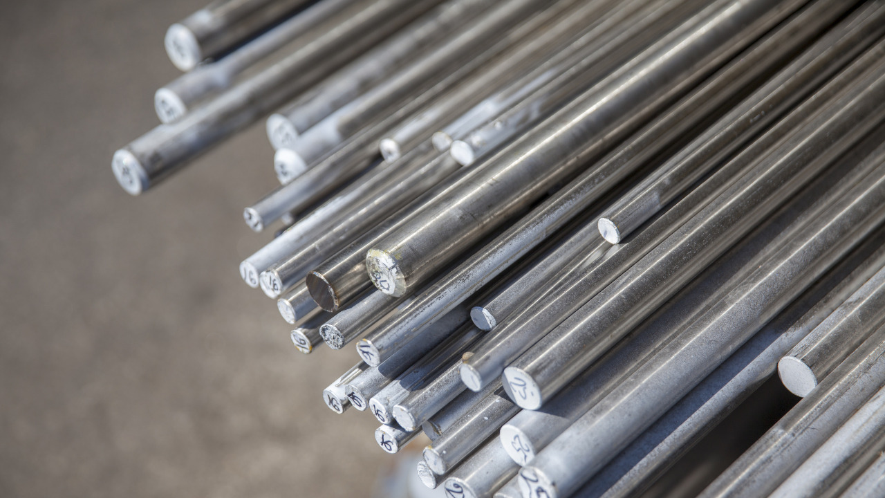
Steel Bars
Classification of Steel Bars based on Surface Characteristics
Based on the surface characteristics, there can be two types of steel bars; plain steel bars and deformed steel bars.
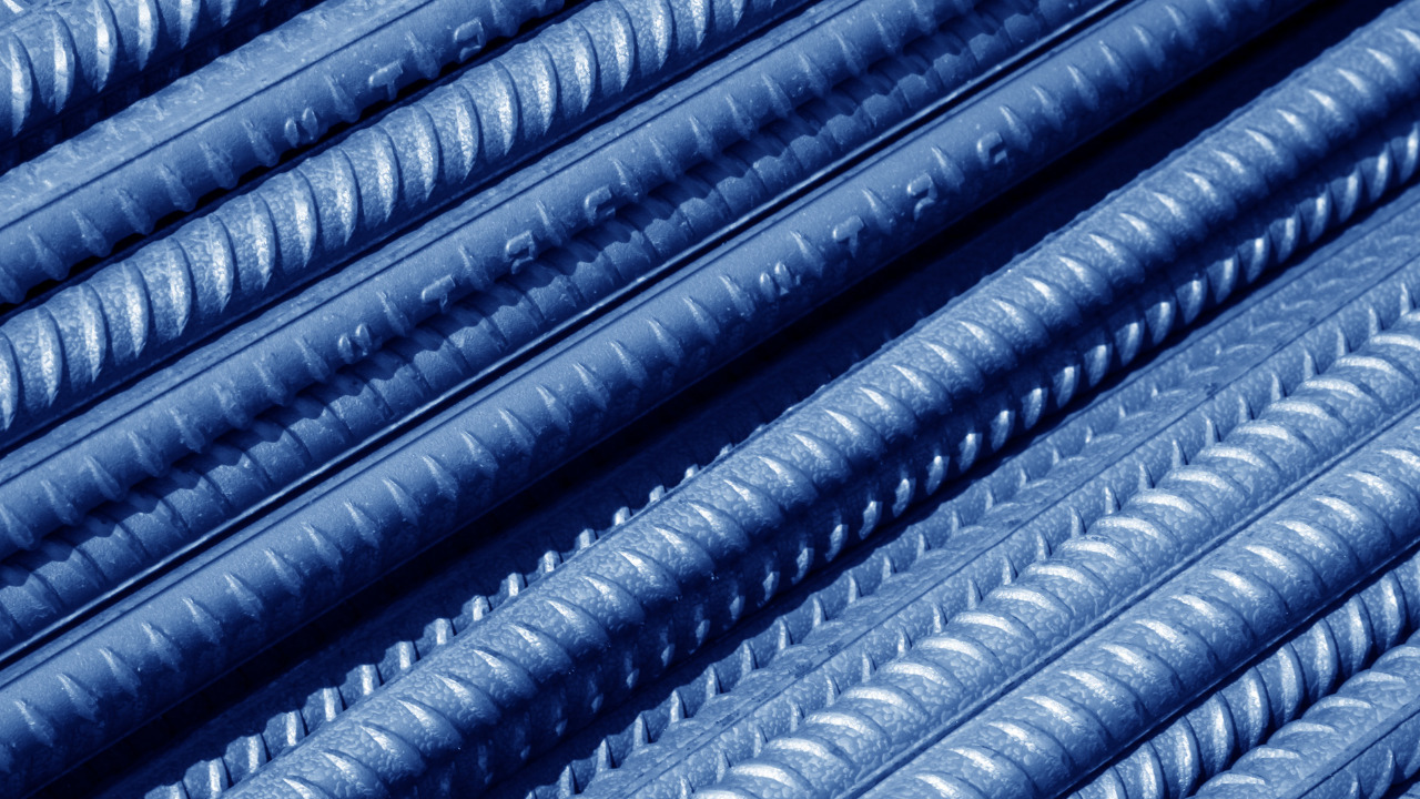
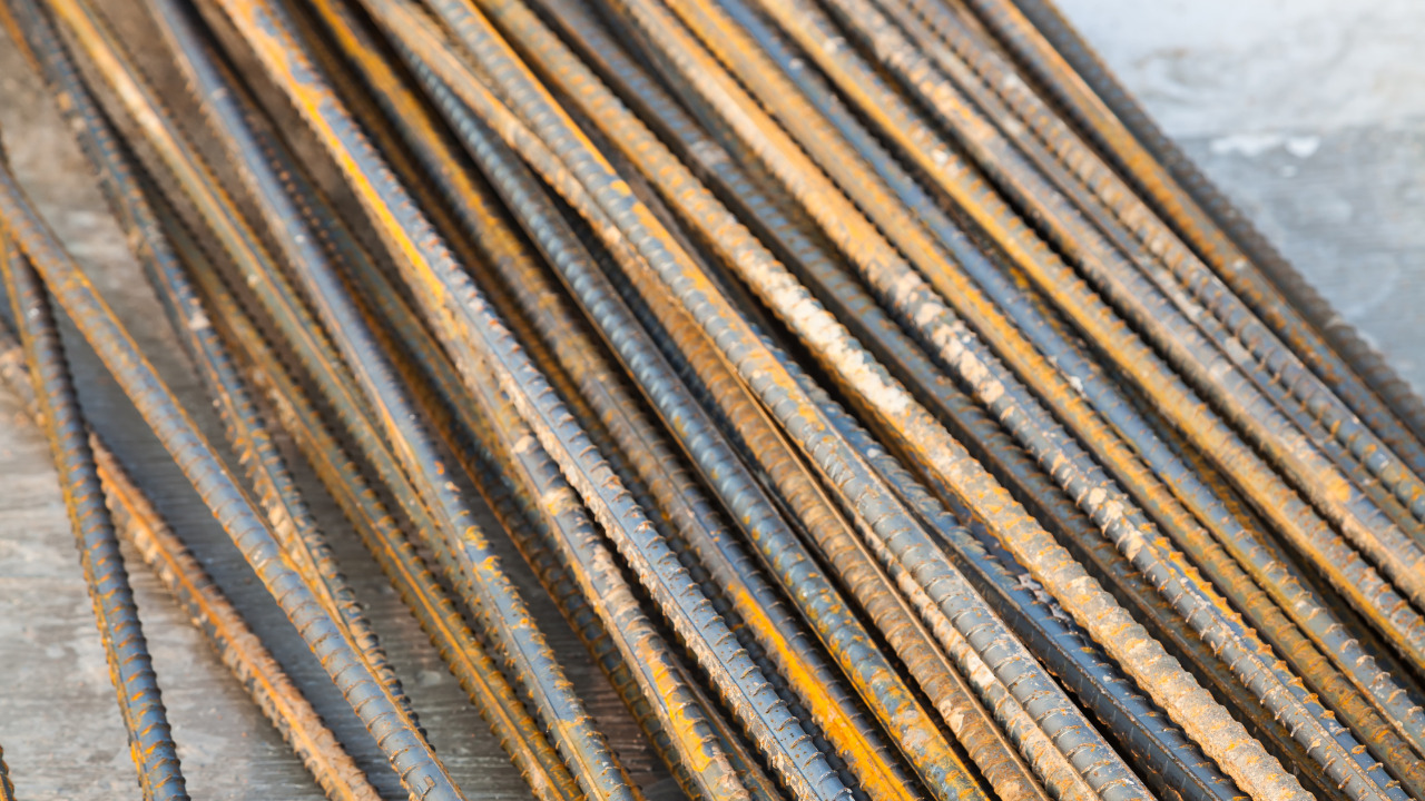
Plain steel bars have a smooth surface and when used in concrete, they resist the loading by adhesion and friction only. On the other hand, deformed bars have longitudinal and transverse deformations called as ribs or lugs on the rebar surface that helps to grip the concrete and interlock the two materials with each other.
Plain or deformed steel bars can be used in the concrete by embedding then at a certain depth (determined from design). Depending the type of function, a concrete member has to serve, the placement of rebars is decided accordingly. However, no matter what type of reinforced concrete member you cast, the side that is anticipated to develop tensile stresses will get the reinforcement.
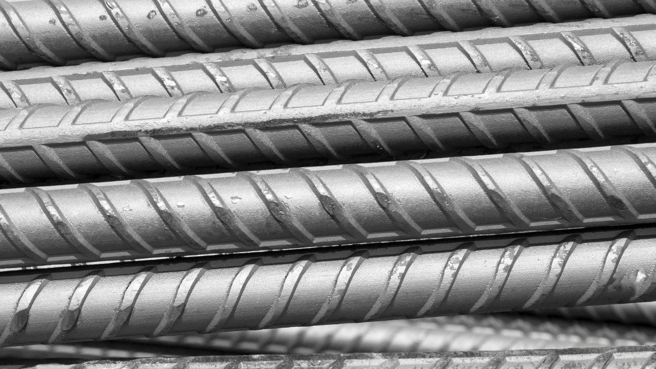
Transverse and longitudinal ribs on deformed steel bars
For instance, in case of a simply supported beam, when transverse loading is applied from the top, the beam flexes or bends such that the bottom part (the part opposite to the load side) is expected to develop tensile stresses and the top part (the one which is on the load side) is expected to develop compressive strength.
The steels bars in this case will be provided at the bottom to cater for tensile strength of the member, preventing it from sudden collapse or large cracking.
On the other hand, if the transverse loading acts on a beam from the bottom, the tensile stresses will develop on the top (the part away from the load side) and the compression will develop on the load side. Therefore, the main flexural reinforcement in the form of steel bars will be provided at the top now.
The use of plain bars is not recommended by the standards in practice to be used in structural concrete members. This is because under the service loading, a pull-out failure is expected to occur and the steel concrete bond will instantly break, collapsing the member in no time.
Classification of Steel Bars Based on Chemical Composition and Treatment
Based on the chemical composition, steel bars can be classified into the following types;
Mild Steel Bars
These bars are the most common of all and serve efficiently for all structural works. They are experimentally found to be a good choice for structures because they provide a blend of strength and ductility and prevent sudden collapse in reinforced concrete members.
High Yield Strength Deformed (HYSD) Bars
As the name indicates, these deformed bars have a very high yield strength which is not definite. The ribs present on the bar surface inhibit longitudinal movement of the bar relative to the surrounding concrete.
When these bars are twisted hot o cold, they further lead to augmentation of the yield, tensile, and bond strength of the bar.
Thermo-mechanically Treated (TMT) Bars
This type of steel bar is in limelight in recent years and for all the right reasons. These bars are extra high strength reinforcing bars that eliminate any form of cold twisting. The treatment process involves subjecting the bars to a short, intensive cooling as they pass through a water-cooling system.
As a result of this reduction in temperature, the surface layer of the bar gets converted into a hardened structure. Following this intensive cooling, the bar is also subjected to atmospheric cooling so that the temperature of its core and surface get equalized. The resulting bar is an improved version of ordinary steel bar and possesses high strength coupled with toughness and ductility.
TMT bars exhibit a definite yield point and can resist very high temperatures (up to 500 degrees Celsius) without losing strength. They also possess excellent bendability and are also capable of withstanding bending and re-bending.
TMT also possess good weldability which means that they do not suffer loss of strength at the weld joints. Their excellent fatigue resistance makes their use extremely advantageous under dynamic loading such as that of an earthquake event.
These bars are available in three grades and the grade number indicates the minimum yield strength in units of MPa.
- TMT 415
- TMT 500
- TMT 550
These bars are used for general concrete reinforcement in buildings, bridges and other concrete structures. They are highly recommended in high-rise buildings and also in seismic-prone areas.
Thermo-mechanically Treated High-Strength Corrosion Resistant (TMT-HCR) Bars
Well, this might sound boring and exaggerating as we are indulging in a deep sea of knowledge about steel reinforcement. However, we tell you this rebar type is the latest and most advanced form of reinforcement that targets a number of mechanical properties of steel.
These bars are concrete embedded ones and depict superior resistance to aggressive and harsh weather conditions. They exhibit thermal resistance at very high temperatures of about 600 degrees Celsius. This amazing resistance to softening at surging temperatures can be attributed to the chemistry involved in making this rebar type.
There is no cold-worked structural zone in the rebar and chemical structure of this steel is appropriately designed for substantially reducing atmospheric and marine corrosion.
The most striking feature of this steel bar is that is provides a unique combination of strength, ductility, bendability and corrosion-resistance. In addition, the deformations on the surface further ensure excellent bond strength with the concrete.
TMT-HCR bars are used in places that are prone to fire hazards and also in areas where the steel reinforcement is vulnerable to getting corroded in a short span of time such as in coastal and marine environments. They are also used in bridges, flyovers, dams, industrial construction, high-rise buildings and underground structures.
Cold Twisted Deformed (CTD) Bars
Cold twisted bars are high strength deformed bars that possess a high yield strength as well as bond strength. In addition, they also result in 40% economy when compared with other steel bars.
Steel Grade and Diameter
Steels bars are available in the market having different grades and diameters. In addition, they may be plain bars, deformed ones, thermos-mechanically treated (TMT) bars, tor bars, etc. The most among these are deformed bars that have lugs or deformations on the surface to prevent slipping of bar relative to concrete and allow good gripping or interlocking between the two different materials.
Deformed bars are available in grade 40, 60, 80, 100 etc. and the number indicates the yield strength of the bar in ksi (kilo pounds per square inch).
As far as the diameter of bars is concerned, they are generally available in diameters between 10 to 40 mm and depending upon a specific member’s design, the bar diameter and grade is selected.
2. Mesh Reinforcement
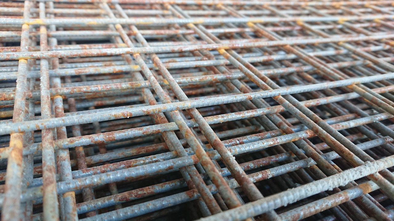
It is also termed as ‘welded wire mesh’ and is an assembly of interconnected steel wires welded at the intersection that forms the shape of a mesh. It provides great strength to the member and also imparts durability to it.
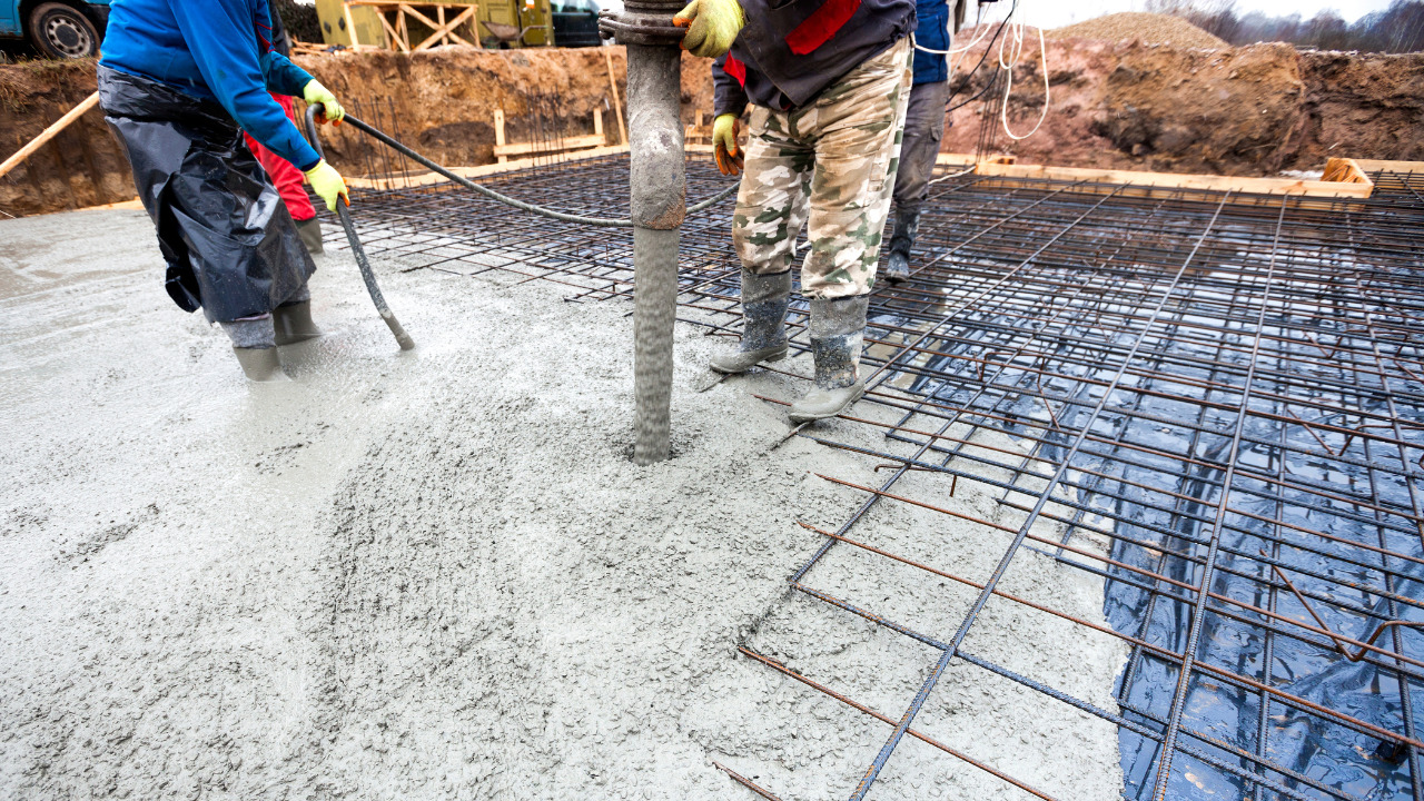
The design of mesh reinforcement involves determining the mesh size and spacing which will depend upon the member requirements and specific applications. The term ‘mesh size’ is used to indicate the spacing between the wires in millimeters. Once it is decided, the mesh is cut to the required shape and size and is then positioned in the concrete formwork. Therein, it is kept in place using metal chairs. The adjacent sheets of steel mesh are tied together at the overlapping areas and secured in place. Following this the concrete is poured all around the reinforcement and appropriate curing ought to be done once the member hardens.
3. Fiber Reinforcement
Unlike other reinforcements added to augment the strength of reinforced concrete (particularly in tension), fiber reinforcement has little to do with improving the strength of a reinforced concrete member.
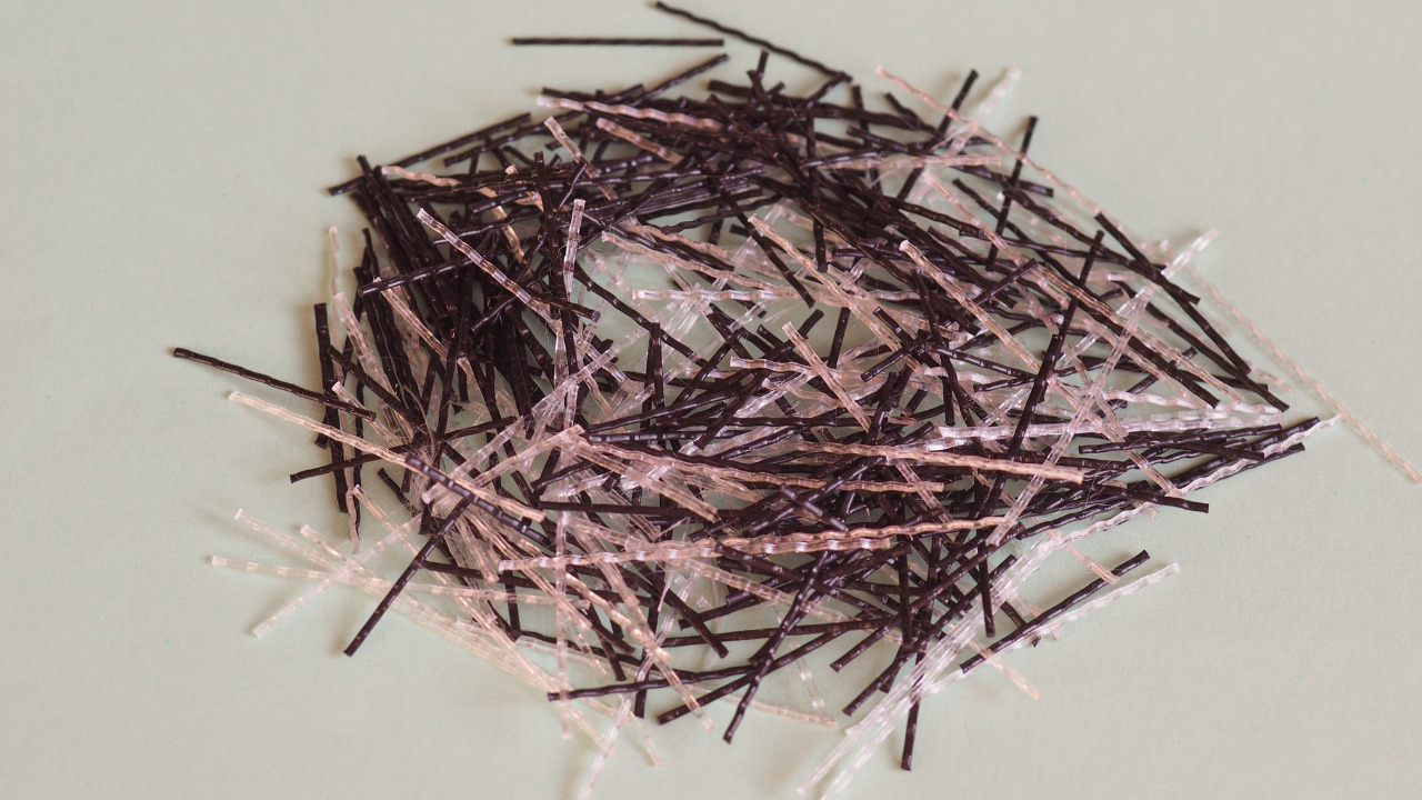
Fiber reinforcement in concrete is in the form of short, discrete and discontinuous reinforcing units added in the wet or plastic concrete mix to improve the member strength post cracking. These fibers can be of different materials, shapes and sizes. These include (but are not limited to) steel fibers, glass fibers, organic fibers, polymeric fibers, wood fibers, carbon fibers, etc.
The mechanism of working of fiber reinforcement is such that when a concrete member begins to exhaust its strength by developing microcracks in the initial stages, the fibers become a source of bridge between these cracks. If no fibers are added in concrete, we expect the cracks to keep opening as the member capacity keeps exhausting. However, if these cracks are inhibited to propagate, the ductility of the member gets augmented and it can take up the loads for a longer duration of time without instantly exhausting its capacity.
Reinforcement Types with respect to Purpose
All the reinforcement that you add in concrete doesn’t necessarily cater to tensile stresses; it can also be added for other purposes such as increasing shear strength of the member, etc.
The following reinforcement types serve some specific function and we will abreast you with each one of them
-
Flexural Reinforcement
Flexural reinforcement is added in reinforced concrete members that flex or bend under the applied loading. When that happens, a part of the member experiences its fibers getting stretched and a part of it experiences its fibers getting compressed.
Since concrete is strong in compression, the part that develops compressive stresses remains strong in its resistance, however, the part in tension is prone to failure. Therefore, flexural tensile reinforcement is to be provided on this side of the member to prevent early and sudden cracking in the concrete.
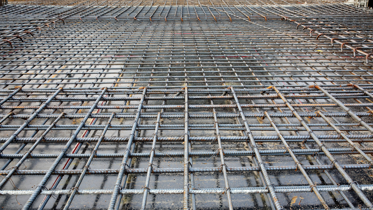
Flexural reinforcement can be in the form of steel rebars that are embedded in the concrete prior to casting and then the concrete is cast all around these bars that are placed at some definite spacing depending upon design.
Given this, flexural reinforcement is provided in reinforced concrete (RC) beams, slabs, foundations, etc. to augment the bending ability and tensile strength of the member.
In case of RC beams, we normally provide main steel reinforcement on the tension side and hanger bars on the other side to hold the shear reinforcement in place and provide a reinforcement assembly that does not open up. As a normal practice, 2 hanger bars are provided and shear ties are in the form of a closed loop.
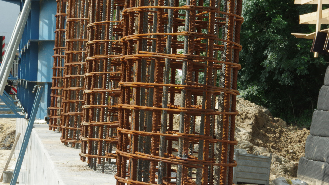
In RC columns, the main flexural reinforcement is usually (and preferably) provided on all sides of the column. However, if owing to some eccentricity, a column is expected to flex or bend in a particular direction, the reinforcement may then be provided on 2 sides depending upon the moment developed.
In case of RC slabs, the main reinforcement again is provided on the tension side. However, a special consideration is given to providing a minimum temperature or shrinkage reinforcement in the other direction. Shrinkage cracking becomes predominant as the exposed surface area of a member increases. This is particularly noticed in concrete slabs because in comparison to their depth, the surface area is very large.
So, what difference does it make if the surface area is large? This is a very pertinent question and here is where the concept of shrinkage in concrete needs to be understood. Shrinkage in concrete is a time dependent process that keeps taking place as the water from concrete escapes the surface. If the process of shrinkage is very expedient (owing to a number of reasons such as very high prevailing temperatures), the concrete will begin to crack.
In case of a concrete slab, when shrinkage will take place, the part which has the main reinforcement owing to anticipated tension will remain safer, however, the other side will begin to crack as the concrete shrinks. To avoid this, some minimal reinforcement is also provided in the other direction to cater to this problem in concrete. This reinforcement is termed as ‘shrinkage or temperature reinforcement’.
The codes of practice have provided guidelines for minimum temperature reinforcement in the slabs.
2. Shear Reinforcement
This type of reinforcement is normally added to increase the shear resistance of a member. Shear resistance is defined as a member’s ability to resist shearing (sliding) between two adjacent planes. Shear failure in reinforced concrete members is very common and ought to be avoided by proper design.
In case of RC beams, shear reinforcement is provided in the form of ties or shear stirrups. These are placed vertically, perpendicular to the main reinforcement of beam, at intermediate intervals to resist shear stresses. The failure by shear is usually in the form of diagonal cracking and these shear ties prevent crack opening and provide adequate shear strength to resist it. The number of legs of stirrup, its diameter and spacing determined from the design procedure and is then checked against the code limits for adequacy. An RC beams fails in shear at the support sections where diagonal cracking begins and if adequate resistance is not available, the cracks propagate towards the neutral axis.
Similarly, in case of RC columns, shear reinforcement is provided in the form of ties or spirals, the latter is normally used for circular columns. The shear ties surround the longitudinal reinforcement and are placed at intermediate spacing all throughout the member length. Spiral or helical reinforcement is similar to ties as it surrounds the main steel; however, the helical reinforcement is provided such that there is no break and the helix covers the entire length of column. As far as shear strength is concerned, helical reinforcements provide greater shear resistance than that provided by shear ties. However, owing to difficulty in placing the spiral reinforcement for columns shapes other than circular, we usually prefer shear ties in columns.
Now, for RC slabs, we do not provide shear reinforcement as a normal practice and in case, the member fails in shear when analyzed, usually other options are considered for improving the shear strength. These options include increasing the slab depth, using a concrete of higher compressive strength, changing the dimensions of the underlying columns, etc. However, in case all these options become difficult to implement for one reason or the other, we may provide shear heads as shear reinforcement in the slab. These heads serve as anchors and are welded with a metal plate such that they remain vertical and resist diagonal cracking in the slab.
Conclusively, shear reinforcement in any reinforced concrete member can either be in the form of shear stirrups (with one or more than one leg and having different shapes such as closed stirrup, U-shaped one, etc.), shear heads, inclined or bent-up bars, spiral or helical reinforcement, etc.
3. Torsional Reinforcement
Torsion can occur in reinforced concrete members due to eccentricity of load or inequality of deformations on two ends of a member. This leads to twisting of the member which is what we call torsion. The design for torsion is more complex in comparison to the design for shear or flexure. However, ignoring its significance is a futile effort of designing a structural member and expecting it to perform under all anticipated conditions.
In case of RC beams, if shear stirrups are adequately designed and they are present in a closed form i.e., not in a U shape or any other open shape, the ties will suffice to resist torsional stresses within the beam. Their distribution along the length of the member must also be properly designed.
In beams, torsion is mostly developed if the line of action of applied transverse load is eccentric with respect to the centerline of the beam. In such case, the beam will (flex) bend and will also twist due to load eccentricity.
Another way to prevent a beam from failing due to torsional stresses is by providing steel bars along the neutral axis of the member. Doing so, the bars will resist any twisting that occurs within the member.
In case of RC columns, mostly transverse helical reinforcement aptly serves the purpose of resisting torsional stresses. The pitch of the spiral reinforcement must adequately be designed so that it does not allows the column to twist at any section along the length. In case of columns, torsional stresses are developed if the two ends of a column show unequal deformations. Therefore, at times, the helical reinforcement will also prove to not be very effective in resisting torsion. You may then need to go for the use of moment frames or shear walls to ensure that the column can effectually withstand the applied loading.
In case of RC slabs, closed stirrups serve a two-fold function. These help in resisting the shear as well as torsional stresses in a slab. Torsion is developed when a slab panel deflects unequally on two of its ends. This unequal deflection causes a part of it to twist relative to the other.
4. Pre-stressing Reinforcement
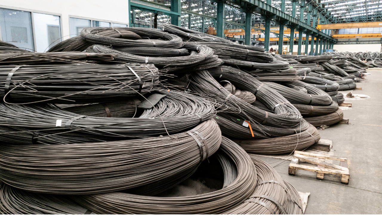
The wires present in the form of coils are twisted to make pre-stressing strands used as pre-stressing reinforcement.
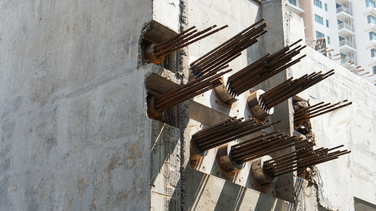
As the name indicates, pre-stressing reinforcement is used to prestress a concrete member to induce artificial stresses in it before it is brought into serviceability. In the process of pre-stressing, the pre-stressing steel reinforcement (strands or wire) is stretched (tensioned) to a certain stress level and this force is later on transferred to the member by releasing the strands.
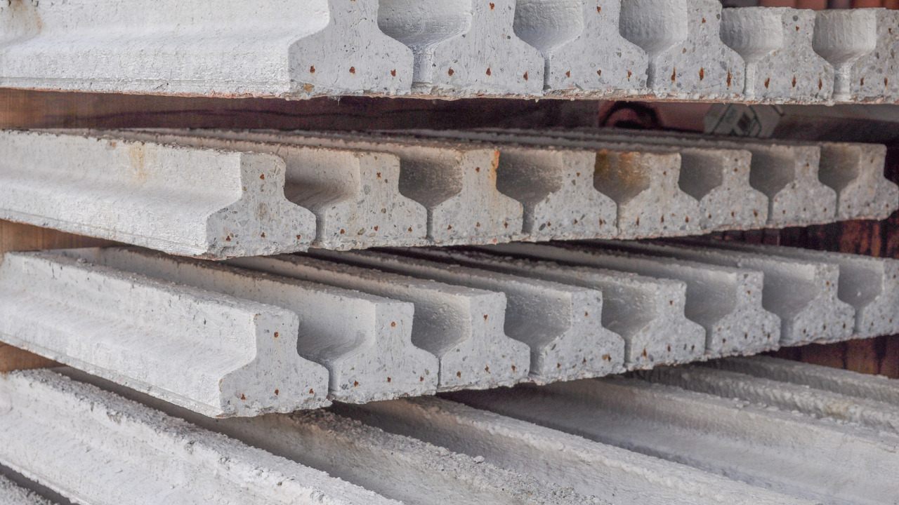
The holes in the members indicate locations where the pre-stressing steel has been curtailed.
There are two steel grades available for pre-stressing reinforcement namely grade 250 and grade 270 wherein the grade number indicates the ultimate strength of reinforcement.
Rusting and Corrosion in Steel Reinforcement
Every construction material known to builders so far, possesses an inherent weakness which although can either be reduced or eliminated in certain cases, it still impacts the performance of the member and the structure as a whole.
For instance, taking a very common example of plain concrete. It was born sick against tensile stresses and poor resistance against tension is the inherent weakness of concrete; that’s where the steel bars sneak in!
Similarly, steel has this inherent weakness of not being able to resist corrosion for a long time. It is bound to get rusted when exposed to moisture and air. So, what actually is rusting?
Rusting is a process of formation of rust (iron oxide) when iron (steel) comes in contact with moisture in the presence of air. The presence of both air and moisture is essential for the corrosion process to commence. In reinforced concrete, moisture can make its way to attack reinforcement through the interconnected voids when the member comes in contact with water.
The formation of rust is the first step that takes place when iron, water and air react. This rust, a powder, occupies more volume than the steel and during the expansion, it exerts tensile forces on the surrounding concrete. In addition, rust breaks the bond between the steel and concrete and when excessive corrosion or prolonged reaction takes place, the composite action between steel and concrete is lost.
This means that steel and concrete will now behave independently in order to bear the applied loading which leaves the concrete at the fag end of bearing the tensile stresses on its own. When that happens, you should not expect your member to be surviving for long. The instant concrete reaches its modulus of rupture, the member will collapse instantly without any prior warning.
Given this, we can succinctly say that for steel, the process of corrosion is an appreciating muddle, the origin of which must either be prevented or eliminated during the member’s service life.
The question arises that how to protect steel from corroding? There are many methods using which you can protect the reinforcement from corroding over time. The following are some of the prevalent methods;
Enamelling
In this process, a flux is melted on the surface of iron in muffle furnace following which a second layer of more fusible glaze is coated on top of it.
Applying Metal Coatings (Galvanizing, Tin Plating, Electroplating)
Metal coatings involve applying a layer of metal coat on top of the reinforcement surface that acts as a barrier or inhibitor for the process of corrosion to commence. In galvanization, a thin film of zinc is coated on the steel surface whereas in tin coating, as the name indicates, a film of tin is coated on the reinforcement against the attack of moisture.
In case of electroplating, metal coatings of chromium, nickel or zinc are applied on surface of iron.
Applying Organic Coatings (Painting and Coal Tarring)
The reinforcement can also be painted to prevent it from corrosion. This involves applying a coat of red lead followed by a coat of enamel or aluminum paint.
Steel-Concrete Composite Action
The term composite action is used to indicate the aggregated performance of two separate materials when they behave as one. Obviously, for this to happen, there has to be some kind of bond between the two independent materials that will increase the friction and help one material grip the other.
In case of reinforced concrete, the most common type of reinforcement is in the form of deformed bars. When wet or plastic concrete is poured all around the steel reinforcement, upon hardening, the composite action gets developed. The lugs or ribs on the bar help steel to interlock concrete within these deformations and when the service loading is applied on the member, both steel and concrete behave as one at the interface.
Another important point to keep in mind about composite action is that at the interface of steel and concrete, the strain in steel must me equal to the strain in concrete for a perfect composite action to exist. If steel and concrete strains show disparity, either the bond between them is deficient or the bond has been broken due to either corrosion or any other reason.
Frequently Asked Questions (FAQs)
What is meant by the term cold twisting in case of reinforcing steel bars?
Cold twisting or cold working is a process in which the reinforcing steel bars are tempered by twisting or bending carried out at room temperature. The purpose of doing so is to increase the bar strength and stiffness and allow it to develop greater resistance to bending and other deformations.
To twist the bars in the process of cold working, specialized bending machines are used and following the twisting operation, the bars are allowed to cool at room temperature.
Cold twisted bars are now used commonly in different reinforced concrete structures such as bridges, highways, massive buildings, etc.
Is there any lower or upper limit to providing steel in a concrete member?
The area of steel to be provided in any reinforced concrete member is not something you must decide by hit and trial. A proper design is to be done to determine the area of reinforcement that will safely bear the applied loading in the service life of a structural member.
However, once the required steel area is determined, it is to be cross-checked using the standard guidelines provided by different codes to ensure that the area neither falls short nor provided in excess to what is required.
It is important to understand as to why there is a lower limit on the steel area and also an upper limit. The lower limit to steel area is to ensure that the steel is actually contributing to catering the tensile stresses developed in the concrete member.
On the other hand, the upper limit to reinforcement is set so that the steel yields prior to crushing of concrete. The advantage of such a design is that the yielding of steel will give warning and the member will not collapse just instantaneously. To ensure this warning before failure, the amount of steel reinforcement must be less than a certain minimum set by the code.
Which standard is used as a guideline for reinforced concrete?
The American Concrete Institute (ACI) has provided standard guidelines about all the dos and don’ts of reinforcement in concrete and the types that are available for a construction work.
This code highlights different types of structural concrete (plain, reinforced, prestressed), the reinforcing materials that can be used in concrete, the necessity and corrosion resistance and the storage and handling of reinforcement.
The storage conditions are important for steel reinforcement to ensure that it does not rust upon reaction with moisture present in the air. In addition, prior to placing the reinforcement in the designated location, it must be cleaned off any dirt or coating that will prevent bond between steel and concrete.
It is recommended to consult the above code to get a detailed insight into the essentials of reinforcement in concrete and what should one consider while opting for a particular type.


