Table of Contents
Standard Followed
ASTM D 1559 or AASHTO T-245
Objective
The Marshall stability test is a part of the mix design procedure for bituminous pavements. Following are the objectives of performing the stability test:
- To anticipate the performance of a bituminous mix prepared using Marshall’s method of mix design.
- To determine the stability and flow values of hardened bituminous mix samples.
- To determine the optimum bitumen content for a particular aggregate grading.
Related Theory
Stability and flow tests are performed on cylindrical specimens after they have been immersed in a water bath at a temperature of 60°C for a period of 30 to 40 minutes. This is to bring the samples to the required temperature prior to loading them in the Marshall testing machine.
Stability Value:
It is the maximum load that a sample can endure in compression till its failure. The value of stability is mathematically calculated once the proving ring reading is recorded corresponding to the point of failure of the specimen.
The multiplication factor of 119.66 is obtained as follows;
Calibration coefficient of the test machine = 12.202 kg/div
If we convert the above factor in SI units of force, we get,
Calibration coefficient (N/div) = 12.202 * 9.807 = 119.66 N/div.
Flow Value:
It is the total deformation (expressed in mm) that a sample shows till the point of failure. It is generally expressed in units of 0.25mm. The flow value is obtained by multiplying the flow gauge reading with the gauge’s least count.
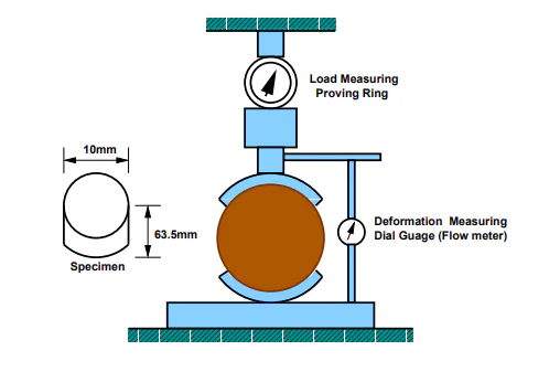
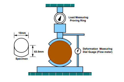
The figure below shows the test setup in which the compacted test specimen is placed between the split loading metal rings. A base plate is present beneath the lower ring. In order to load the sample in compression, the base plate moves up at a specific, predetermined loading rate.
The applied load can be traced from the proving ring and the commensurate deformation can be recorded from the flow gauge present adjunct to the test assembly. The stability and flow values are therein calculated mathematically and the results are plotted.
Stability Correction Factors
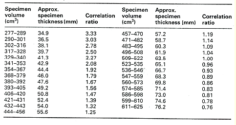
It is probable that during the casting of test specimens, the sample/s either falls short of the requisite dimensions (diameter or height) or in excess of the same. In that case, a correction factor is to be applied to the stability value calculated. The table to be referred to in this case is given below:
In case the exact value of volume or thickness is not present in the table above, the correction ratio can be interpolated linearly.
Apparatus
- Marshall testing machine, a compression testing machine with a proving ring attached that reports the magnitude of the applied load. The
- Flow-meter, to measure the deformation of the compacted test specimen when it subjected to a compressive load
- Water bath, to bring the specimens to the required test temperature
- Marshall test specimens
Fig.: Marshall compacted test specimen
Fig.: Marshall test setup
Test Specifications:
- The samples must have a diameter of 102mm and a height of 64mm.
- For a particular mix design, at least three samples are to be prepared.
- The compacted test specimens are to be kept in a water bath at 60°C for 30 to 40 minutes.
- The test is strain-controlled and the loading rate is to be kept 51 mm/min i.e., the base plate of the test machine travels upward at the eponymous rate.
Test Procedure
- Bring the molded samples to the required temperature i.e., 60°C by placing them in a water bath for a time span of 30 to 40 minutes.
- Remove the specimens from the water bath and place them in the Marshall testing machine in a such way that the machine applies a load on the sample’s surface area and not the cross-section.
- Adjust the proving ring and flow gauge to zero before loading the sample.
- The machine exerts a compression force on the sample and at a particular load, the specimen fails in compression. Note down the value of peak load from the proving ring.
- Also, record the corresponding vertical deformation of the sample from the flow gauge and the time elapsed for the test.
- Calculate the flow value and stability value as follows:
- Apply stability correction by consulting the relevant charts.
- Plot the following requisite graphs that explain the trend between various parameters determined during the test.
- Bitumen content versus corrected Marshall stability value
- Bitumen content versus Marshall flow value
Observations and Calculations
Least count of flow dial gauge =
Calibration coefficient of proving ring =
| Sample No. | % Bitumen Content | Maximum Proving Ring Reading (div.) | Stability Value (kN) | Flow Dial Gauge Reading (div) | Flow Value (mm) | |
| Measured | Corrected | |||||
| 1 | ||||||
| 2 | ||||||
| 3 | ||||||
The stability and flow values are to be checked against the Marshall mix design specifications given in the following table.
Graphs
- Plot a graph between the corrected Marshall stability value and the percentage bitumen content, taking the former on the y-axis and the latter on the x-axis. The general graphical trend is shown below:
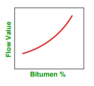
- Also plot a graph between the deformation (i.e., the Marshall flow value) as ordinate and the percentage bitumen content as abscissa. The general variation is shown in the following plot.
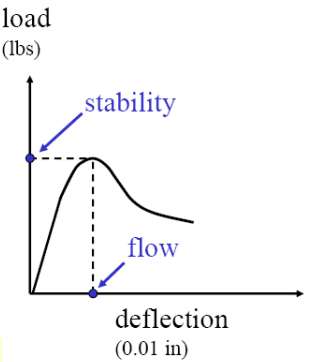
- A load-deflection curve can also be plotted, taking the stability value (corrected) on the y-axis and the corresponding deformations on the x-axis. The general graphical trend is given as follows:
Determine the optimum bitumen content by taking out the average value of bitumen content from the plots above.
Results
Marshall Stability Test Outcomes
| Test Property | Experimental Value |
| Marshall Corrected Stability Value (kN) | |
| Marshal Flow Value (mm) | |
| Optimum bitumen content |
Test Precautions
- The sample mixing, compaction, and preparation must be carried out at the specified temperature.
- Load the specimen such that it is exactly at the center of the test machine.
- After removing from the water bath, the stability and flow test must not be delayed and should be performed immediately within 30 minutes of the sample being taken out of the bath.
Discussion
Selecting the required proportions of aggregates (fine and coarse), fillers, and bitumen for the design of pavement is an essential step. The aggregates must be carefully examined for their compliance with the standard specifications and the proportions selected should serve the cause aptly. It is to be kept in mind that the traffic density (high, medium, or low) also impacts the mix design process.
A mix with a very high value of stability but a low flow value is never desirable. This is because a pavement constructed with such an approach is likely to develop unsightly cracks once heavy vehicular loads assail its strength. Therefore, the optimum proportions are ought to be determined for the pavement design.

