Table of Contents
Orifice
The flow of water in a pipe running full is under the influence of pressure forces. In order to measure the flow under pressure, a number of flow measurement devices can be employed such as mouthpieces, nozzles, pitot static tube etc.
However, the simplest and effortless method of measuring discharge is by using an orifice that simply means a hole or aperture that produces an outflow of water. For the purpose of flow quantification, an orifice is located in the side or base of a tank or reservoir as shown in the figure below;

Fig. 1: Orifice at the Side of a Tank
In the above figure, H is the head above the centerline of the orifice and z is the elevation of the orifice from the base of tank. This head is liable for the flow of water through the orifice. This is owing to the fact that greater is the available head, greater is the velocity through the orifice (as per Torricelli’s Theorem). Consequently, for a constant area of opening, greater velocity points to greater discharge.
Factors controlling discharge through an orifice
The flow rate through an orifice depends on the following factors;
- Head available above the centerline of orifice
- Size of Orifice (includes large orifice, small orifice, etc.)
- Shape and form of orifice (included circular orifice, rectangular orifice, etc.)
To ensure accurate flow measurement and to reduce frictional losses, a sharp-edged orifice should be avoided

Fig. 2: Sharp-edged orifice
The Concept of Vena Contracta
When water is permitted through an orifice, the streamlines come closer to each other in the area the orifice is located.
However, at a particular section of the jet a little away from the orifice towards the discharging end, the streamlines come the closest possible. This section is termed as the ‘vena contracta’. At this section, the area of the water jet that is expelled out of the orifice is least. Again, this contraction hinges on the head, shape and size of the orifice.
A possible reason contributing to the convergence of streamlines is that they are unable to abruptly change the flow direction. Therefore, making a smooth transition through the orifice, the streamlines continue to converge till they trespass the orifice section.

Fig. 3: Vena Contracta
Classification of Orifice
Orifices may be classified based on a number of factors, some of which are related to geometry and the others related to outflowing conditions.
1.Based on Size
- Small Orifice
- Large Orifice
- If the opening size of the orifice is small relative to the available head that triggers flow through it, the orifice is termed as small. A mathematical limit on the size of small orifice is D<H/5 , where D is the diameter or opening size of the orifice and H is the head.
- On the other hand, large orifices have the opening (D) greater than H/5
2.Based on Shape
- Circular
- Rectangular
- Square
- Triangular

Fig. 4: Orifices based on shape
3.Based on Shape of Entrance or Upstream Edge
I)Sharp-Edged Orifice
- A sharp-edged orifice provides a sharp entry of water through it. This may lead to some local turbulence around or near the orifice.
II)Bell-Mouthed Orifice
- A bell-mouthed orifice, as the name indicates, provides a smooth transition for water to flow out and therefore, losses due to friction are likely to minimize.
4.Based on Discharge Condition
I)Free Discharge Orifice
- A free discharge orifice outflows water into the atmosphere and once the jet escapes, the entire pressure energy of water is converted into kinetic energy. Therefore, the jet is subjected to atmospheric pressure (i.e., zero absolute pressure) the instant it leaves the orifice. A free discharge orifice is also shown in Fig. 1.
II)Submerged Orifice
- In case of a submerged orifice, the water that is discharged from one container goes to another and therefore, it still possesses some pressure energy depending upon the available head in the latter container.
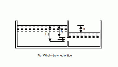
Fig. 5: Submerged Orifice
Hydraulic Coefficients of an Orifice
While dealing with orifices, its necessary to figure out the parameters that affect the flow through it. This is to encounter practicality and to make sure every theoretical statement is made to sound real. For an orifice, we have 3 hydraulics coefficients namely:
I)Coefficient of Contraction (Cc)
Cc= Area of Jet at Vena Contracta / Area of Orifice
Its value is always less than unity because the expelling jet has the least area at vena contracta.
It is not possible to determine the coefficient of contraction experimentally. Therefore, the experimental value is mathematically computed as:
(Cc )exp = (Cv )exp* (Cd )exp
II)Coefficient of Velocity (Cv)
Cv= Actual Velocity at Vena Contracta / Theoretical Velocity
The theoretical velocity is given by Torricelli’s Theorem as vth=√2gH
Its value is actually less than 1, but lies very close to it. For sharp-edged orifices, its value is found more.
Experimentally, the coefficient of velocity is found by formulating an equation of the profile of jet as it leaves the orifice. Hence, using distance -speed relation the actual value of velocity is determined as;
vth=√((gx2)/2y)

Fig.6: Experimental Determination of Cv and Cd
Where x is the horizontal distance of any point on the expelled jet from the orifice and y the vertical distance of the same point from the centerline of orifice.
III)Coefficient of Discharge Cd
Cd=(Actual Velocity*Actual Area)/(Theoretical Velocity*Theoretical Area)=Cv*Cc
Its value is also less than 1.
Experimentally, the coefficient of discharge is found by measuring the outflow of water through the orifice and noting the corresponding time and dividing it by the theoretical discharge i.e.,
Cd=Q/(Aorifice*vth )=(V/t)/(Aorifice*√2gH)
Discharge Equation for Small Orifices
When dealing with small orifices, it is fair enough to assume that the flow velocity through orifice remains constant across its depth. Making this assumption makes it easier to formulate the discharge equation as;
Q=Cd*A*√2gH
Discharge Equation for Large Orifices
For large orifices, it’s presumptuous to ignore the velocity variation that takes place through the section of orifice once the jet forces its way out due to pressure forces. Therefore, in this case, as shown in the figure, we take a small strip of area and integrate it between the limits of orifice size.
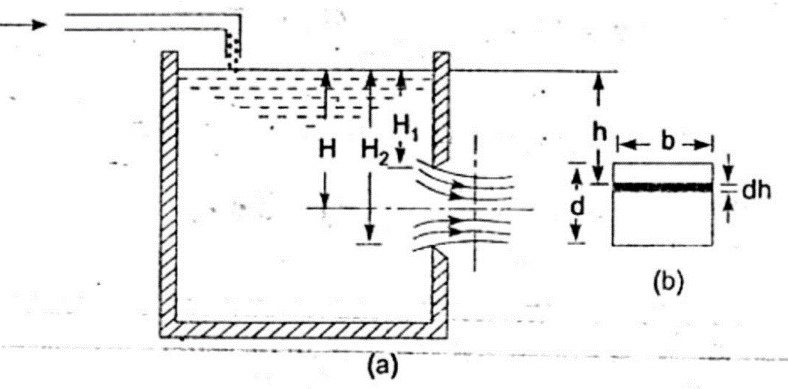
Fig. 7: Large Rectangular Orifice
The final discharge equation becomes:
Q=Cd*(2/3)*b*√2g*[H23/2-H13/2]
Where b is the breadth of orifice.