Table of Contents
Principle
- If a truss is in equilibrium, then each of its joints must also be in equilibrium.
- The method of joints consists of satisfying the equilibrium equation for forces acting on each joint.
- ∑Fx = 0 ∑Fy = 0
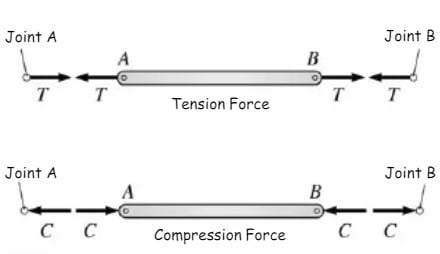
- Recall, that the line of action of a force acting on a joint is determined by the geometry of the truss member.
- The line of action is formed by connecting the two ends of each member with a straight line.
- Since direction of the force is known, the remaining unknown is the magnitude of the force.

Procedure
- If possible, determine the support reactions
-
Draw the free body diagram for each joint. In general, assume all the force member reactions are tension (this is not a rule, however, it is helpful in keeping track of tension and compression members).
-
Write the equations of equilibrium for each joint,∑Fx = 0 ∑Fy = 0
-
If possible, begin solving the equilibrium equations at a joint where only two unknown reactions exist.Work your way from joint to joint, selecting the new joint using the criterion of two unknown reactions.
-
Solve the joint equations of equilibrium simultaneously.
Tips
- The joints with external supports always connect with two truss members.
- Thus many times, the analysis starts from analyzing the supports.
- Therefore very often the analysis begins with finding the reaction forces applied at the supports.
- Pay attention to symmetric systems and zero force members.
- Identification of these special cases sometimes will make the whole analysis way easier.
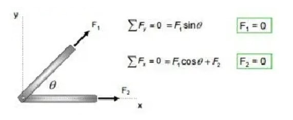
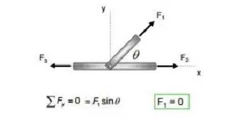
Zero Force Members
Case 1
Case 2
Practical Example
Since direction of the force is known, the remaining unknown is the magnitude of the force.

Step 1 (Free body Diagram)
Free-body diagram of entire truss. Calculating the reactions is a good place to start because they are usually easy to compute, and they can be used in the equilibrium equations for the joints where the reactions act.

Step 2 (Equation of Equilibrium)
Equilibrium equations for entire truss

Step 3
Free body diagram of Joint C

Step 4
Equilibrium equations for joint C. It is a good idea to assume all members in tension (forces point away from the joint, not towards it). Then, after solving the equilibrium equations, you will know immediately that any member force found to be negative must be compression.

Step 5
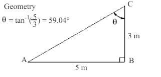
Step 6 (Trigonometry)
Using Angle= 59.04° in Eqs. 4 and 5 and solving simultaneously gives

Writing “(T)” after the numerical value shows that the member is in tension. We had arbitrarily assumed member BC to be in tension. We then found that the member force was negative, so we know that our assumption was wrong. Member BC is in compression, and we show this by writing a positive “6.0” followed by “(C)”
Step 7
Free body diagram of joint B
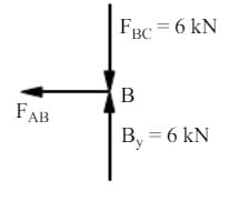
Step 8
Step 9
Step 10 (Final Result)