Table of Contents
Standard Used
ASTM D 1037
Objective
Following are the objectives of performing this experiment:
- To determine the compressive strength of wooden cubes parallel and perpendicular to the grains
- To investigate the stress-strain relationship in wooden cubes to determine the modulus of elasticity and modulus of stiffness
- To discern the anisotropic behavior of wood when it is subjected to compression under different sample orientations.
Related Theory
Compressive Strength:
When a material is loaded in compression, the maximum load it can withstand without crushing or rupturing is called its compressive strength.
For a wooden sample, anticipatingly, the failure will be brittle, and the material will fail without prior warnings. However, the peak load that the wooden sample bears, also depends on the orientation of its grains relative to the line of action of externally-applied compressive load.
Modulus of Elasticity:
The modulus of elasticity of wood is the ratio of stress to strain within the elastic range of the material. The strain values can be obtained from deflection gauges attached to the wooden samples during the test, whereas, the stress is calculated using applied load and the contact area of the sample. Mathematically,
The significance of elastic modulus is that it aids in determining the deformation response of material under any applied loading in the elastic range.

Modulus of Stiffness:
The stiffness of a material is the energy it absorbs within the elastic range while being elastically deformed under the applied loading. In other words, the resistance of a material to deformation caused by an externally-applied load within the elastic range is an index of its stiffness. Mathematically,

Anisotropic behavior of Wood:
If the line of action of an applied load varies but the strength or mechanical properties of material remain the same, the material is said to be isotropic. Contrary to this is an anisotropic material, which shows different mechanical properties subject to varying lines of action of external load. Wood is an anisotropic material. In the context of compressive strength, when the load is applied parallel and perpendicular to the grains of the wooden sample, the crushing load varies.
Load application is Parallel to the Grains
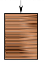
When a compressive load is applied on a wooden sample such that the line of action of the external load and the orientation of the grains become parallel, the wooden sample shows a relatively high compressive strength.

Investigating the stress-strain relationship unveils that, the grains of the wooden sample act as separate columns and each column contributes to bearing the applied load. Therefore, if a particular grain column fails or gets malformed, the others play their part in withstanding the crushing load.
Load application is Perpendicular to the Grains
When the applied loading is perpendicular to the grains of the wooden sample, the sample fails at a relatively less load value. This is because any malformed grain reduces the overall load-bearing capacity of the specimen.

Apparatus
- 500 kN Universal Testing Machine, to load the sample in compression till its rupture
- Wooden cubes
- Deflection dial gauges, to determine the corresponding value of strain with each load increment
- Vernier Caliper, to measure the dimensions of wooden cubes, including their length, breadth, and height.

Fig. (L): Universal Testing Machine
Test Procedure
- Measure the dimensions of the wooden sample using a vernier caliper.
- Place the wooden sample in the universal testing machine such that the grain fibers are parallel to the applied compressive load.
- Attach the deflection dial gauges to the sample.
- Start loading the sample in compression.
- Note down the deflection reading from the dial gauges for each regular load increment.
- When cracks begin to appear, remove the deflection gauges and load the sample to failure. Note down the peak or crushing load.
- Using the peak load and contact area, calculate the compressive strength of the wooden cube.
- Calculate the stress and strain values and plot a graph between them to determine the modulus of elasticity and modulus of stiffness.
- Repeat the above procedure by orienting the sample in such a way that the grain fibers are perpendicular to the applied load.
Observations and Calculations
Least Count of deflection dial gauge =
1)When grains are parallel to the applied load
Sample Dimensions
Length, l =
Width, b =
Height, h =
Contact area, A =
| Sr. No. | Applied Load, P (kN) |
Deflection Dial Gauge Reading (div.) |
Deflection,
δ (mm) |
Percentage Strain,
ϵ=(δ/h)×100 (-) |
Stress,
σ=P/A (MPa) |
k=P/δ (N/mm) |
| 1. | ||||||
| 2. | ||||||
| 3. | ||||||
| 4. | ||||||
| 5. | ||||||
| 6. |
The stress corresponding to peak-load is the compressive strength of the wooden sample.
Graph
- A graph is plotted between the stress and strain values, taking strain as abscissa and stress as ordinate. The slope of this graph gives the modulus of elasticity (E) of the wooden sample.
- Similarly, another graph is plotted between load (P) on the y-axis and deformation on the x-axis. The slope of the initial part of this graph gives the modulus of stiffness (k).
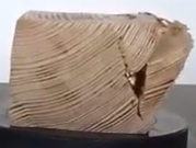
Failure Pattern

2)When grains are perpendicular to the applied load
Sample Dimensions
Length, l =
Width, b =
Height, h =
Contact area, A =
| Sr. No. | Applied Load, P (kN) |
Deflection Dial Gauge Reading (div.) |
Deflection,
δ (mm) |
Percentage Strain,
ϵ=(δ/h)×100 (-) |
Stress,
σ=P/A (MPa) |
k=P/δ (N/mm) |
| 1. | ||||||
| 2. | ||||||
| 3. | ||||||
| 4. | ||||||
| 5. | ||||||
| 6. |
The stress corresponding to peak-load is the compressive strength of the wooden sample.
Graph
- A graph is plotted between the stress and strain values, taking strain (ϵ) as abscissa and stress (σ) as ordinate. The slope of this graph gives the modulus of elasticity (E) of the wooden sample.
- Similarly, another graph is plotted between load (P) on the y-axis and deformation (δ) on the x-axis. The slope of the initial part of this graph gives the modulus of stiffness (k).
Failure Pattern

Results
When grains are parallel to the applied load
Compressive Strength, = MPa
Modulus of Elasticity, E = MPa =
Modulus of Stiffness, k = N/mm
When grains are perpendicular to the applied load
Compressive Strength = MPa
Modulus of Elasticity, E = MPa
Modulus of Stiffness, k = N/mm
Test Precautions
- Make sure the sample is centered between the plates or platens of the UTM. This is to ensure that the centroid of the sample coincides with the centroid of the loading plate, producing no eccentricity.
- Carefully read the deflection dial gauge reading for each load increment.
- While performing tests on a UTM, stay at a distance from the machine while the test is being performed.
Discussion
Compression testing aids in determining the mechanical properties of wood. However, these properties are subject to change depending upon the type of wood taken. Additionally, a small wooden sample is, at times, not representative of the material and, therefore, testing a wooden beam or a larger sample may result in differing properties w.r.t the magnitudes. Nevertheless, the general trend remains the same.


