Table of Contents
Behavior of RC Beams Under Gravity Load

Beam Test
In order to clearly understand the behavior of RC members subjected to flexure load only, the response of such members at three different loading stages is discussed.
Mechanics of RC Beams Under Gravity Load
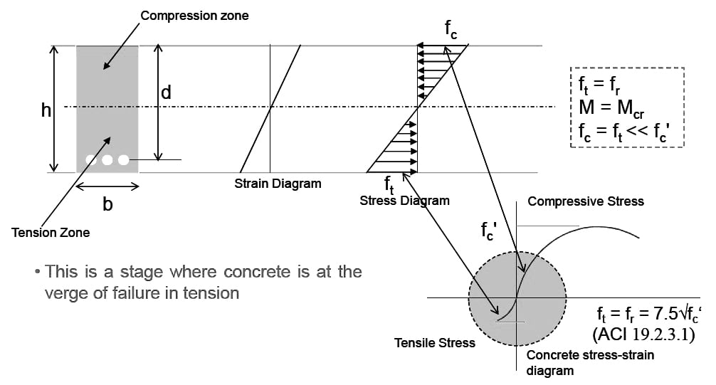
1. Un-cracked Concrete – Elastic Stage:
At loads much lower than the ultimate, concrete remains un-cracked in compression as well as tension and the behavior of steel and concrete both is elastic.
2. Cracked Concrete (tension zone)
Elastic Stage With increase in load, concrete cracks in tension but
remains un-cracked in compression. Concrete in compression and steel in tension both behave in elastic
manner.
3. Cracked Concrete (tension zone) – Inelastic (Ultimate Strength) Stage
Concrete is cracked in tension. Concrete in compression and steel in tension both enters into inelastic range. At collapse, steel yields and concrete in compression crushes.
Stage-1:
Behavior
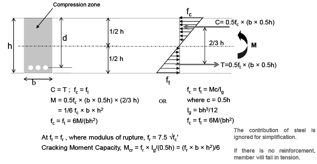
Calculation of Forces
Stage-2:
Behavior

Calculation of Forces
Stage-3:
Behavior

Calculation of Forces

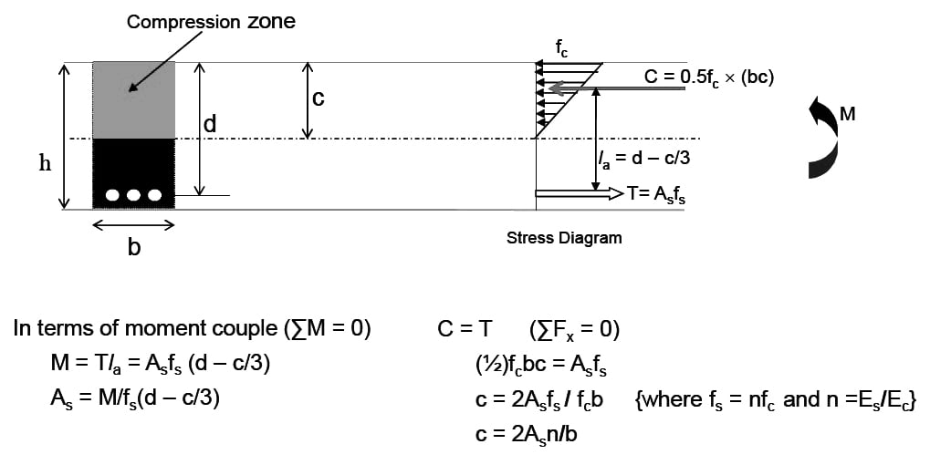
Basic Assumptions: (ACI 22.2)
- A plane section before bending remains plane after bending.
- Stresses and strain are approximately proportional up to moderate loads (concrete stress ≤ 0.5fc′).
- When the load is increased, the variation in the concrete stress is no longer linear.
- Tensile strength of concrete is neglected in the design of reinforced concrete beams.
- The bond between the steel and concrete is perfect and no slip occurs.
- Strain in concrete and reinforcement shall be assumed proportional to the distance from neutral axis.
- The maximum usable concrete compressive strain at the extreme fiber is assumed to be 0.003.

- The level of the centroid of the steel. Also if the strain in the steel ɛs is less than the yield strain of the steel ɛy, the stress in the steel is Esɛs. If ɛs ≥ ɛy, the stress in Figure 9 steel will be equal to fy

ACI Code Recommendations
1. Strength Design Method (ACI 4.6)
- According to the ACI Code, the RC Members shall be designed using the strength design method.
- In the strength design method, the loads are amplified and the capacities are reduced.
- The loads are amplified in the following manner.
Load combinations (ACI 5.3)
WU = 1.2 WD + 1.6 WL
MU = 1.2 MD + 1.6 ML
- Where; WD = Dead load and WL = Service Live load
WU = Amplified load or Ultimate load
MU = Amplified moment or Ultimate moment - According to strength design method the resisting member flexural capacity calculated from specified dimension (size of members) and material strength called as the nominal flexural capacity Mn = Asfy (d – a/2) shall be reduced by multiplying it with strength reduction factor Φ = 0.9, to get the design flexural capacity (Md).
Md = Φ Mn ; Φ = 0.9
For no failure; Φ Mn = Mu
2. Nominal Flexural Capacity of RC Member
- The nominal flexural capacity of RC Members shall be calculated from the conditions corresponding to stage 3.
- ACI-R21.2.2 — The Nominal Flexural Strength (ΦMn) of a RC member is reached when the strain in the extreme compression fiber reaches the assumed strain limit of 0.003, (i.e. strains at stage 3.)
- In other words, the member finally fails by crushing of concrete, even if steel in tension has yielded well before crushing of concrete.
3. Maximum Reinforcement (Asmax): (ACI 21.2.2)
- When concrete crushes at εc = 0.003, depending on the amount of steel (As) present as tension reinforcement, following conditions are possible for steel strain (εs)
1. εs = εy Balanced Failure Condition, Brittle Failure
2. εs < εy Over reinforced condition, Brittle failure
3. εs > εy Under Reinforced Condition, Ductile Failure
- For relative high amount of tension reinforcement, failure may occur under conditions 1 & 2, causing brittle failure. It is for this reason that ACI code restricts maximum amount of reinforcement in member subjected to flexural load only.
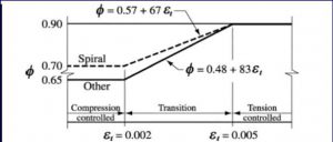
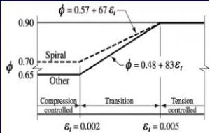
- To ensure ductile failure & hence to restrict the maximum amount of reinforcement, the ACI code recommends that for tension controlled sections (Beams) εs = εt = 0.005

- From equilibrium of internal forces,
- ΣFx = 0 → C = T
0.85fc′ab = Asfy …………(a)
- From similarity of triangles, in strain diagram at failure condition,
- c/εu = (d – c)/εs
- c = dεu/(εu + εs)
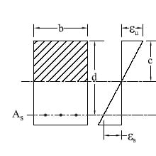
- For ductility in Tension Controlled sections (Beams)
- εs = εt = 0.005 (ACI 10.3.5) and at failure εu = 0.003 (ACI R10.3.3),
- c = dεu/(εu + εs)→ c = 0.375d and, a = β1c = β10.375d
- Therefore, when a = β10.375d, As = Asmax in equation (a).
Hence equation (a) becomes,
0.85fc′β10.375db = Asmaxfy
Asmax = 0.31875β1bd fc′/fy … (b)
318-11, 10.2.7.3 — Factor β1 shall be taken as 0.85 for concrete strengths fc′ up to and including 4000 psi. For strengths above 4000 psi, β1 shall be reduced continuously at a rate of 0.05 for each 1000 psi of strength in excess of 4000 psi, but β1 shall not be taken less than 0.65.
Asmax = 0.31875 β1bd fc′/fy … (b)
For β1 = 0.85; fc′ = 3 ksi ; and fy = 40 ksi
Asmax = 0.0203 bd;
ρmax = Asmax / bd = 0.0203 which means 2 % of effective area of concrete.
ρ = Reinforcement ratio = Area of steel / Effective area of concrete
β1 = 0.85; fc′ = 3 ksi ; and fy = 60 ksi
Asmax = 0. 0135 bd; which means 1.35 % of gross area of concrete
4. Reinforcement (Asmin): (ACI 9.6.1.2)
- At every section of a flexural member where tensile reinforcement is required by analysis, the area As provided shall not be less than that given by ρminbwd where, ρmin is equal to 3√ (fc′)/fy and not less than 200/fy.
For a statically determinate beam, this reinforcement shall be doubled.
- ρmax and ρmin for various values of fc′ and fy
|
Table 01: Maximum & Minimum Reinforcement Ratios |
||||||
|
fc′ (psi) |
3000 |
4000 | 5000 | |||
|
fy (psi) |
40000 |
60000 | 40000 | 60000 | 40000 |
60000 |
|
ρmin |
0.005 |
0.0033 | 0.005 | 0.0033 | 0.0053 |
0.0035 |
| ρmax | 0.0203 | 0.0135 | 0.027 | 0.018 |
0.0319 |
0.0213 |
Design Steps
The design involves the following steps:
- Selection of Sizes
- Calculation of Loads
- Analysis
- Design
- Drafting
1. Selection of Sizes
Minimum depth of beams as per ACI 9.3.1
| Support Conditions | Minimum h |
| Simply supported | l /16 |
| One end continuous | l /18.5 |
| Both ends continuous | l /21 |
| Cantilever | l /8 |
Where l is the span of the beam
For fy other than 60,000 psi, the expressions in Table shall be multiplied by (0.4 + fy/100,000).
2. Calculation of Loads
Loads are calculated as follows:
Wu = 1.2WD + 1.6WL
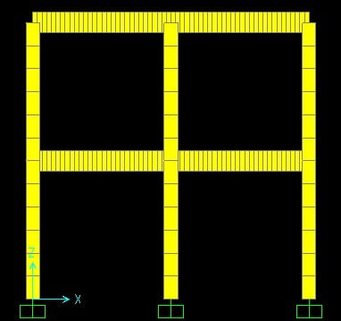
3. Analysis
- The analysis of the member is carried out for ultimate load including self weight obtained from size of the member and the applied dead and live loads.
- The maximum bending moment value is used for flexural design.
4. Design
- Assume “a”
- Then calculate area of steel using the equation,
As = Mu/ {Φfy (d – a/2)}
- Confirm the ‘a’ value using the equation,
a = Asfy/0.85fc′b
- Perform trial and success procedure until same As value is obtained from two consecutive trials

Flexure capacity check
Mn = Asfy (d – a/2) [Nominal capacity]
ΦMn = ΦAsfy(d – a/2) [Design capacity]
To avoid failure, ΦMn ≥ Mu
5. Drafting
Based on the design, drawings of the structural members are prepared showing the dimensions of member and detail of reinforcing bars.
Practical Example
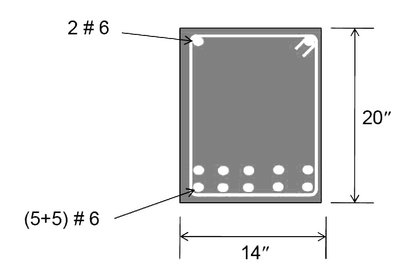
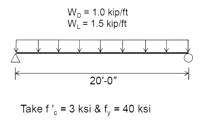
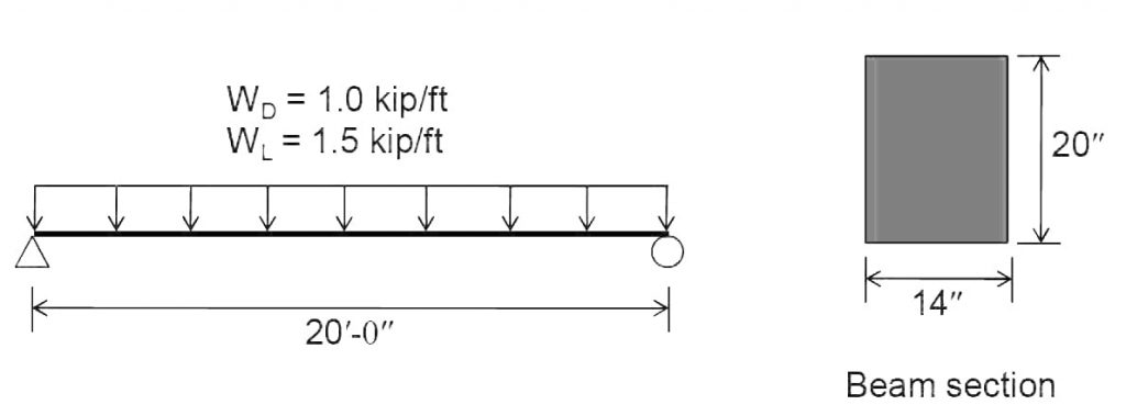
Flexural Design of Beam as per ACI: Design the beam shown below as per ACI 318-14.
Solution:
Step No. 01: Sizes.
For 20′ length, hmin = l/16 = 20*12/16 = 15″
However we select 20″ deep beam
Width of beam cross section (bw) = 14″ (assumption)
Step No. 02: Loads.
Self weight of beam = γcbwh = 0.15 × (14 × 20/144) = 0.292 kips/ft
Wu = 1.2WD + 1.6WL
= 1.2 × (1.0 + 0.292) + 1.6 × 1.5 = 3.9504 kips/ft
Step No. 03: Analysis.
Flexural Analysis:
Mu = Wu l2/8 = 3.9504 × (20)2 × 12/8 = 2370.24 in-kips

Step No. 04: Design.
Design for flexure:
ΦMn ≥ Mu (ΦMn is Mdesign or Mcapacity)
For ΦMn = Mu
ΦAsfy(d – a/2) = Mu
As = Mu/ {Φfy (d – a/2)}
Calculate “As” by trial and success method.
First Trial:
Assume a = 4″
As = 2370.24 / [0.9 × 40 × {17.5 – (4/2)}] = 4.25 in2
a = Asfy/ (0.85fc′bw)
= 4.25 × 40/ (0.85 × 3 × 14) = 4.76 inches
Second Trial:
As = 2370.24 / [0.9 × 40 × {17.5 – (4.76/2)}] = 4.35 in2
a = 4.35 × 40/ (0.85 × 3 × 14) = 4.88 inches
Third Trial
As = 2370.24 / [0.9 × 40 × {17.5 – (4.88/2)}] = 4.37 in2
a = 4.37 × 40/ (0.85 × 3 × 14) = 4.90 inches
“Close enough to the previous value of “a” so that As = 4.37 in2 O.K
Check for maximum and minimum reinforcement allowed by ACI:
ρmin = 3 √(f′ /fy) ≥ 200/fy
3 × √(3000 /40000) = 0.004
200/40000 = 0.005
Therefore, ρmin = 0.005
Asmin = (ρmin)(bw)(d) = 0.005 × 14 × 17.5 = 1.225 in2
ρmax = 0.85β1(fc′/fy){εu/(εu + εt)}
εt = Net tensile strain. When εt = 0.005, Φ = 0.9 for flexural design.
β1= 0.85 (for fc′ ≤ 4000 psi
ρmax = 0.85 × 0.85 × (3/40) × (0.003/(0.003+0.005) = 0.0204 = 2 % of area of concrete.
Asmax = 0.0204 × 14 × 17.5 = 4.998 in2
Asmin (1.225) < As (4.37) < Asmax (4.998) O.K
Bar Placement:
10 #6 bars will provide 4.40 in2 of steel area which is slightly greater than required.
Other options can be explored. For example,
8 #7 bars (4.80 in2),
6 #8 bars (4.74 in2),
or combination of two different size bars.
Step No. 05: Drafting