
Angle beams contain two legs that converge at a right angle to one another to form an L-shaped structure. The two legs may have similar or different lengths depending on how they will be utilized. L-shaped angle beams are regularly employed to secure a flooring system to a building’s foundation because of its dependably stable small structural depth.
Before making a design of T and L beam in flexure, you have to understand these beams’ structure proficiently. The T or L Beam is named when the slab and beam produce the cross sections with typical T and L shapes in a monolithic reinforced concrete construction. If you work as a structural steel fabricator, this steel beam is probably well known to you, and you have produced several of them throughout your career.
You are not, however, the only player in the market. Many rivals produce bulk angle beams for customers whose business you want to secure. L beams are a structural element for light loads or a supporting element for heavier loads.
They offer more strength than a Flat Beam and are both small and light. Use them to fasten your own constructions, join a channel to extrusion, or make a corner between plates.

In the casting of reinforced concrete floors/roofs, forms are built for beam sides, the underside of slabs, and the
entire concrete is mostly poured at once, from the bottom of the deepest beam to the top of the slab.


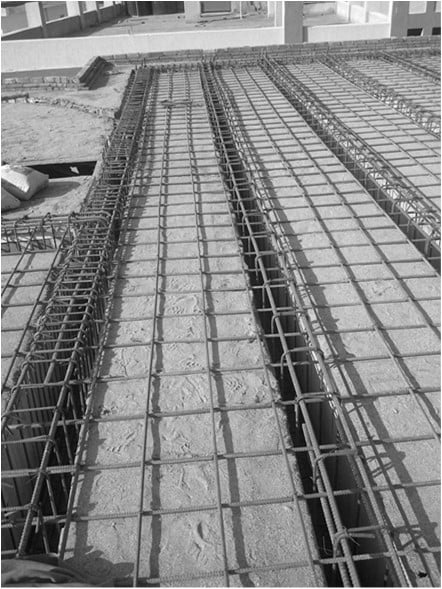


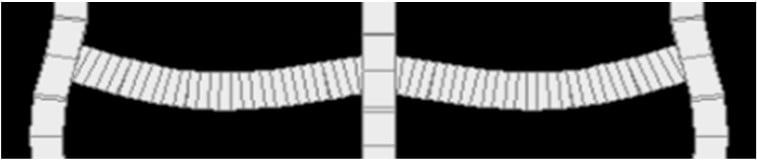

Table of Contents
Positive Bending Moment
- In the analysis and design of floor and roof systems, it is common practice to assume that the monolithically placed slab and supporting beam interact as a unit in resisting the positive bending moment.
- The slab becomes the compression flange, while the supporting beam becomes the web or stem.

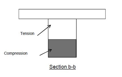
Negative Bending Moment

In the case of a negative bending moment, the slab at the top of the stem (web) will be in tension while the bottom of the stem is in compression. This usually occurs at the interior support of a continuous beam.
ACI Code Provisions for T and L Beams
- For T and L beams supporting monolithic or composite slabs, the effective flange width bf shall include the beam web width bw plus an effective overhanging flange width in accordance with ACI Table 6.3.2.1
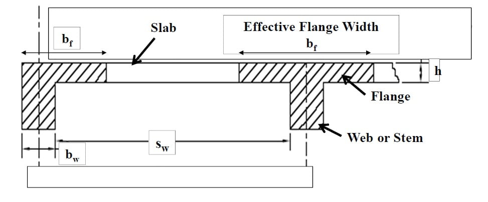
- Calculation of Effective Flange Width (bf) (ACI 6.3.2.1)
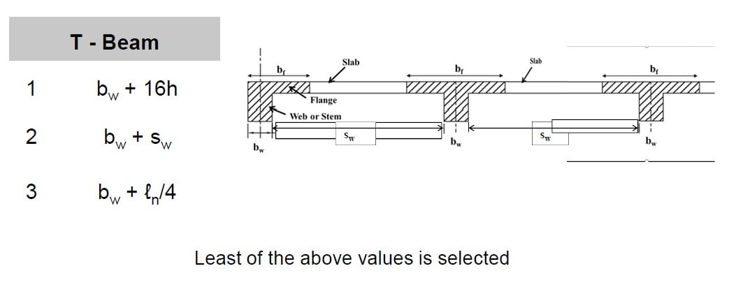
- Where bw is the width of the beam, h is the slab thickness, sw is the clear distance to the adjacent beam, and ℓn is the exact length of the beam.
- Calculation of Effective Flange Width (bf) (ACI 6.3.2.1)
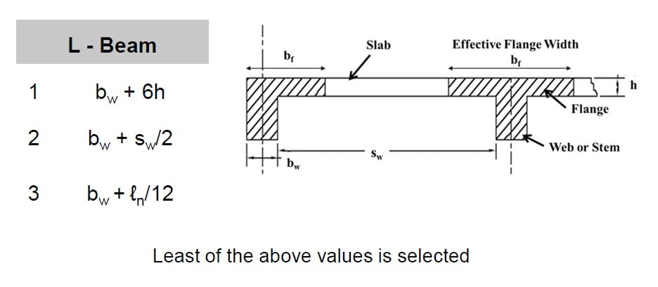
Where by is the width of the beam, h is the slab thickness, SW is the clear distance to the adjacent beam, and ℓn is the exact length of the beam.
Design Cases
- In designing a T-Beam for a positive bending moment, there might exist two conditions:
- Condition 1. The depth of the compression block may be less than or equal to the slab depth i.e. flange thickness (a ≤ h)
- In such a condition, the T-Beam is designed as a rectangular beam for positive
bending, with the width of the compression block equal to bf.

Condition 2. The compression block may cover the flange and extend into the web (a ˃ h) In such conditions the T-Beam is designed as a true T-beam.

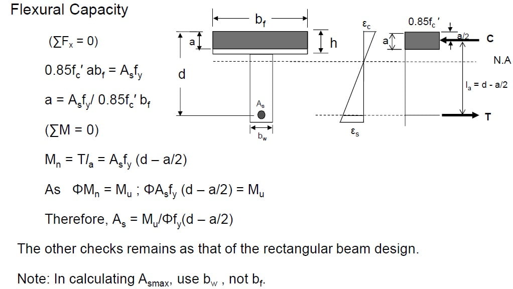
Design of Rectangular T-beam
Flexural Capacity
When a ≤ h

Practical Example
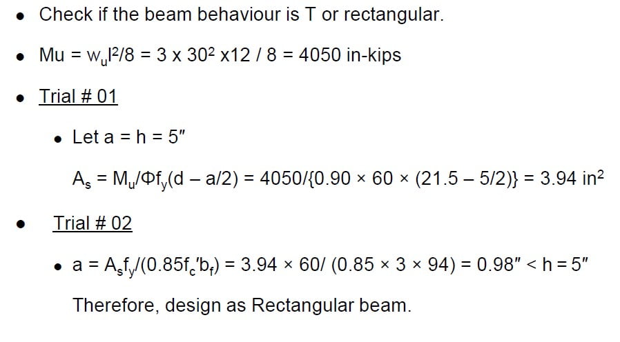
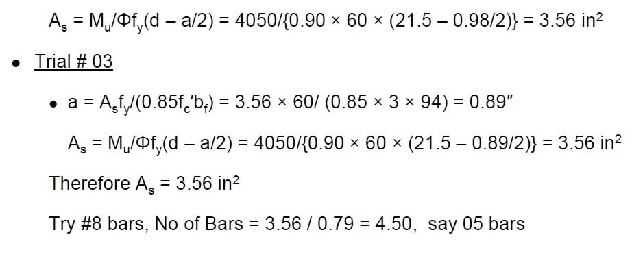
The hall’s roof has a 5” thick slab supported on a beam with 30 feet c/c and 28.5 feet clear span. Adjacent beams are having 9 feet clear distance and have been cast monolithically with the slab. Overall depth of the beam
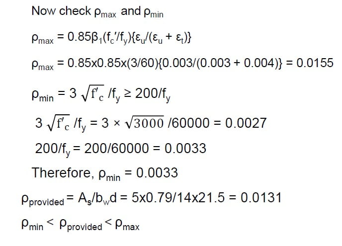
(including slab thickness) being 24 in and the width of the beam web being 14 in. Calculate the steel reinforcement area for the beam for a total factored load (including self-weight of a beam) of 3 k/ft. Use fc′ = 3 ksi and fy = 60 ksi.

Drafting


