When an element is subjected to any load (tensile or compressive), moment or twisting, it withstands the applied action through the inherent material strength and its geometry.
With each load increment, the material begins to deform on the microscopic level initially in the elastic range and then in the plastic range which entails material deformation that is visible to the naked eye.
To this deformation, resistance is provided by the material in the form of stresses. When the applied load or moment induces stresses in the material par its capacity, the material fails to resist any further load and collapses.
Table of Contents
Strain
It is a dimensionless number that represents the amount of deformation incurred in a member when it is subjected to any applied load or moment.
The amount of strain depends upon the applied load as well as the material characteristics.
Types of Strain
1)Axial strain
(tensile and compressive strains) occurs when an element is loaded axially i.e., the line of action of applied load coincides with the longitudinal axis of the member. In this case, the member either expands or elongates (tensile straining), or contracts or shortens (compressive straining). In both cases, the cross-section of the member shows an alteration. Mathematically, strain can be calculated as,
Where the numerator quantifies the deformation in the member and the denominator is the member length. Axial tension is positive showing an increase in the member length, whereas axial compression is negative, depicting shortening of the member.
Fig.: Axial (Tensile) Strain causing member elongation
The axial deformation of a member depends upon the magnitude of applied load and the modulus of elasticity of the material the member is made from.
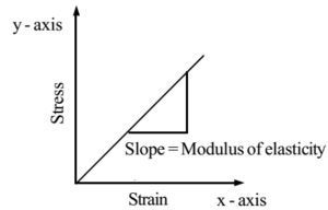
Modulus of Elasticity (E): It is the ratio of stress to strain and depicts the material’s resistance to the applied loading in the elastic range. In other words, the slope of the linear stress-strain plot in the elastic range gives the modulus of elasticity of the material.
The modulus of elasticity is a material property and shows the material’s behavior in the elastic range. For example, the elasticity modulus of steel is 200 GPa and that of concrete is between 30 and 50 GPa.
2)Shear strain or angular distortion
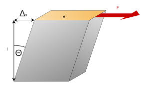
It occurs when an element is subjected to a shear force that tends to slide the layers past each other, causing shearing. It is measured in radians and the mathematical expression for computing shear strain is given by;
Where τ is the shear stress and G is the bulk modulus of elasticity also called the modulus of rigidity.
Fig.: Angular distortion in a member subjected to a shear force, F
The shear strain in a member depends upon the shearing load as well as the modulus of rigidity of the material.
Modulus of Rigidity (G): The shear modulus of elasticity is also a material property and is equal to the ratio of shear stress to shear strain and shows the material’s resistance to any angular distortion or shearing. Mathematically, the shear modulus of a material is determined by knowing its elastic modulus and Poisson’s ratio as;
Where v is the Poisson’s ratio of the material.
Poisson’s Ratio
When a material is subjected to an axial load (tension or compression), the axial strain produces a corresponding transverse straining perpendicular to the longitudinal axis of the member. The ratio of this transverse strain to the longitudinal strain is termed Poisson’s ratio.
Fig.: The concept of lateral strain corresponding to longitudinal strain
Mathematically, it is given by,
The value of Poisson’s ratio is always less than 1 (usually between 0.1 and 0.45), since the longitudinal strain is more than the lateral or transverse strain in a member.
Stress
Stress is the force per unit area generated within an element as a result of an applied load or moment when the material resists a change in its geometry or straining. The magnitude of stress depends upon the intensity of applied loading, the geometry of the element as well as the inherent material properties of the element.
Mathematically, stress within an element can be calculated as;
Where P is the applied load and A is the area perpendicular to it.
Depending upon the nature of the applied load, stress within an element is subject to variation.
Types of Stresses
1)Axial stresses
(tensile and compressive stresses) are developed when an axial load triggers an axial deformation in the material.
2)Flexural stresses
They are developed in a flexural member when is subjected to a load that produces a bending moment or the moment itself.
3)Shear stresses
They are developed due to shear forces tending to produce a distortion in the member.
4)Torsional stresses
They are produced in a member when it is subjected to twisting.
5)Thermal stresses
They are developed within a member when temperature fluctuations spark thermal straining.
Hooke’s Law
According to Hooke’s law, the stress is proportional to strain within the elastic limit of a material. Mathematically,
When the proportionality sign is replaced by equality, a constant of proportionality is introduced which is the modulus of elasticity (E) of the material.
It is to be noted that the above equation holds when the applied load produces a strain within the elastic zone of the material. Beyond the elastic limit, the stress and strain no longer show a linearly proportional relationship.
This is because beyond this limit, the material begins to deform permanently and all the stages of plastic straining cumulate to cause the ultimate rupture or collapse of the member.
Strength Limits
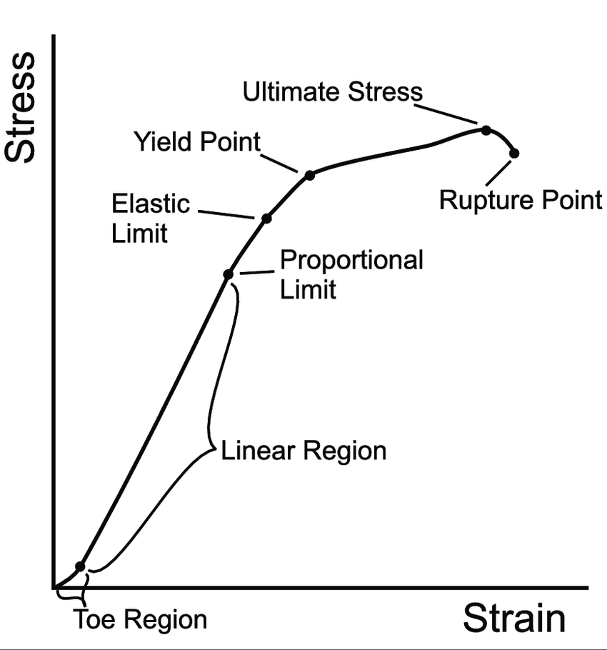
In general, when a member is loaded, the deformations can be recorded for each increment of load using strain gauges. If we plot a graph between the applied load in the form of stress and the corresponding deformation in the form of strain, a stress-strain plot is obtained. From the graph, one can easily identify and comprehend various stages of loading and the corresponding material behavior.
Fig.: Graph showing strength limits when a material is loaded axially
The above figure shows the general stress-strain plot, with strain plotted as abscissa and stress as ordinate. The general strength limits encountered are explained as follows;
1)Proportional Limit:
It is the point on the stress-strain plot till which the stress is proportional to strain. The graph shows a linear variation up to this limit. Proportional limit is difficult to determine and hence, it is assumed to coincide with the elastic limit of the material.
2)Elastic Limit:
This limit on the plot shows the point till which the applied loading produces a strain within the elastic range of the material. This means that if any load is applied in the elastic range, the material deforms but when the load is removed, the material recovers its original shape without any permanent deformation.
3)Yield Limit:
The yield limit indicates the onset of material yielding. It is generally regarded as the point when the material gives an instantaneous warning of failure by showing an increase in strain for a constant stress value. Ductile materials have a well-defined yielding point whereas for brittle materials this limit is usually not defined since the material approaches collapse immediately post-yielding.
4)Ultimate Strength:
The ultimate strength of a material is the peak load a material can withstand without collapsing.
5)Rupture Strength:
It is the stress corresponding to the final collapse of the material. In other words, it is the breaking stress at which the material fails.
Material Response to Applied Loading
1)Ductile Materials
Ductile materials give an appreciable warning before failure. In reinforced concrete structures, this warning or signal is given in the form of yielding of steel that results in cracking in the tension zone prior to the actual collapse of the member.
Therefore, the use of steel reinforcement in concrete not only enhances the tensile properties of concrete but also makes the member ductile.
Fig.: General stress-strain curve for ductile materials
The typical stress-strain plot for ductile materials (e.g., steel) is shown above. As the load is applied, the material deforms elastically till the elastic limit beyond which the material begins to yield. During yielding, the member keeps straining at a constant load value.
As the material yields, plastic deformation commences and the bonds in the material break. As a result, the particles rearrange themselves post-yielding and the ability to withstand loading again takes a hike. This can be seen from the graph as the strain-hardening zone.
The material reaches the maximum load it can possibly tolerate and this is termed its ultimate strength. After this, the material strength begins to decrease in the strain-softening (or necking zone) and it finally collapses at the rupture stress.
Corollaries
- Greater is the grade of steel, greater is its yield and ultimate strength. However, the yield zone shrinks and the material fails at a relatively lower strain value.
- Increasing the carbon content in steel increases its ultimate strength but decreases its ductility.
- The modulus of toughness (that directly indicates the total amount of energy absorbed by the material as it ruptures) decreases as we increase the steel grade.
The figure below shows the comparative stress-strain graphs for high carbon, mild steel, wrought iron, and pure iron. It is to be noted that high-carbon steel depicts the highest ultimate strength and fails at the lowest strain value. Contrarily, pure iron has the least ultimate strength but shows appreciable ductility, which is often sought in reinforced concrete structures.
2)Brittle Materials
Brittle materials such as cast iron do not an give appreciable warning prior to the actual collapse. The figure below shows a stress-strain graph for a cast-iron specimen subjected to tension.
Fig.: General stress-strain cure for brittle materials
Initially, when the load is applied, the material deforms in the elastic range. It is to be noted that for brittle materials, the elastic and yield limit lie very close to each other and the latter is often not defined.
With further load increments, the material begins to deform plastically until it attains the peak strength without prior warning/s and ultimately collapses.
Brittle materials therefore fail suddenly and there is very little time between the material reaching its ultimate strength and that of its collapse.


