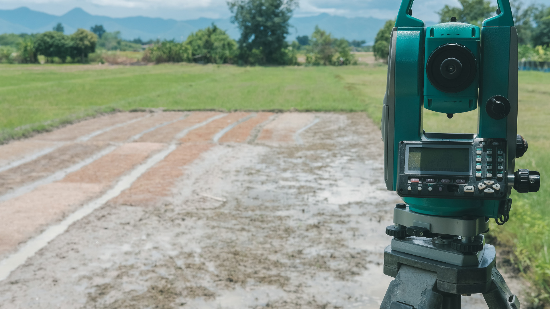
During engineering surveys, irregular plane regions are hard to measure. Hence, engineers utilize an instrument Planimeter, otherwise named as Platometer. This tabletop instrument measures irregular plane areas. It just requires a plan view of that irregular area drawn on a sheet. There was a time when these gauges were common and inexpensive but now have been replaced by digital tools.
Table of Contents
History of Planimeter
- In 1818, Johann Martin Hermann, a Surveyor by profession, invented a planimeter, a gadget that follows the curve of the boundary with a pointy needle associated with a measuring wheel that changes the length of boundary up to the required capacity.
- In 1854, Jacob Amsler-Laffon assembled the main reasonable, viable and progressed planimeter.
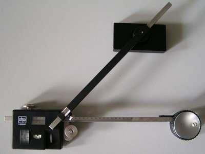
Figure 1: Planimeter by Jacob Amsler
Parts of a Planimeter
Components and figure of planimeter are given below:

Figure 2: Components of planimeter
1)Tracing Arm
Tracing arm controls situation of leading pointy needle toward one side with help of hinge joint.
2)Tracing Point
It shows movement of needle point connected to tracing arm and helps for moving on the outline of the area to be measured.
3)Anchor Arm
This part is utilized to manage anchor position or needle point location on the plan. Its one end is connected with weight and opposite to integrating unit.
4)Weight and needle point
It is additionally named as anchor. A fine needle is situated at base of the heavy square. This needle point is anchored at essential station on the drawn plan.
5)Clamp
Clamp is used to fix the length of tracing arm without any extension.
6)Hinge
The tracing arm and anchor arm are connected by hinge to the integrating unit by assistance of which arms can turn about their axis.
7)Tangent Screw
Tangent screw is used to extend the tracing arm up to required length.
8)Index
Index is a location where all the measuring arrangements like wheel dial are located.
9)Wheel
Wheel is fixed in integrating unit which help to measure the tracing length and to set 0 scale.
10)Dial
Dial is only scale to set zero at the underlying point utilizing setting wheel.
11)Vernier
It is separated in to 100 sections and is attached with settings wheel.
Types of Planimeter
Five major types are given below:
1)A linear Planimeter
This type has a rod named tracer arm on completion of which comes this point T. It cannot move along a straight line and is limited yet another way is to join the terminal to a fixed axis so wheels rotate simultaneously.
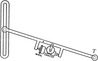
Figure 3: A linear planimeter
2)Amsler polar planimeter
Amsler polar planimeter is handy to measure an irregular and self-assertive shaped area. This gadget traces the boundary of the shape with respect to origin. The wheel at the hinge shows the measurement of area.
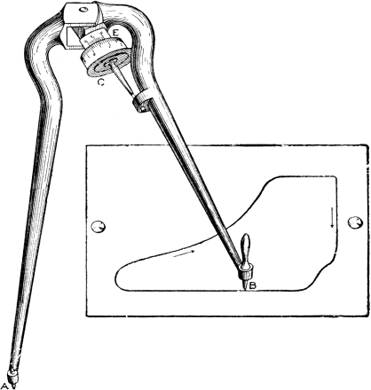
Figure 4: Amsler Polar Planimeter
3)Polar planimeter
Tracer point cannot proceed along a circle. By making a pivot point between tracer and auxiliary arm whose one end pole is fixed, we can move it.
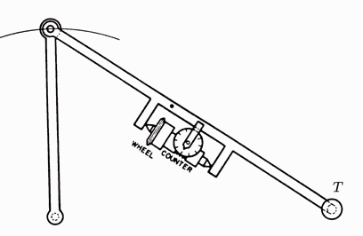
Figure 5: A Polar Planimeter
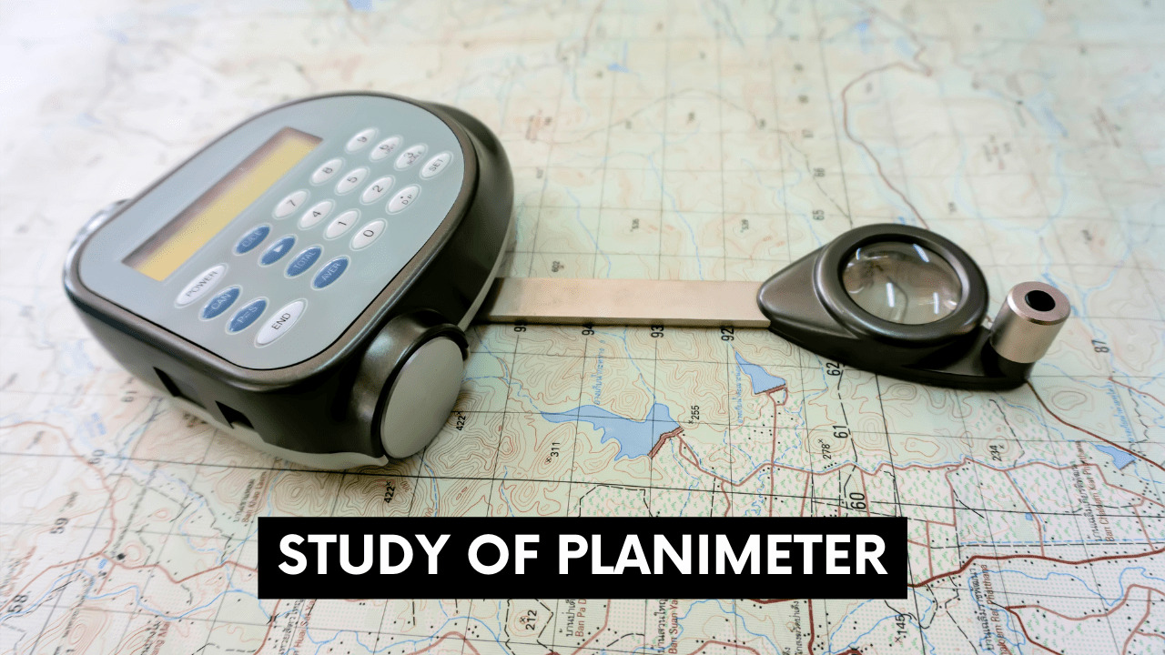
4)Digital Planimeter
Digital planimeter is an advanced gadget and have built in nickel-cadmium storage battery. A turning encoder has replaced the integrating wheel by mechanical planimeter. An electronic circuit estimates beats of turning encoder and area is shown in display screen in digital form.

Figure 6: Digital Planimeter
5)Prytz’s Planimeter
This invention was made in 1875. It is an extremely simple gadget comprising of rod at its ends bend at right angles. Prytz referred it as “stang planimeter,” stang means rod in Danish language.
Figure 7: Prytz’s Planimeter
Procedure of Planimeter
- Place record arm on the tracing arm at required scale precisely by utilizing clamp and movement screw. Avoid wrinkleless of the sheet for accuracy.
- Set the anchor point constant on paper inside the boundary for little external keep.
- Set focus points on external border line of plan and place tracing arm precisely over it.
- Take initial reading for dial, wheel and Vernier.
- Proceed tracing point along border of plan and terminate at beginning point.
- During movement of tracing arm note zero rotations clockwise and anticlockwise way. Repeat observing readings on dial, wheel and Vernier lastly perusing.
Mathematical expression of Planimeter
To calculate area by this device: A = M (FR-IR +10N+C)
As, M = constant to be multiplied for distinctive scales
N = Quantity of 0 (original state) passing a marked point. Positive when clockwise and negative if Anti-clockwise.
C = constant of planimeter distinctive for distinctive scales. It is balanced if anchor stays inside boundary but outside its zero.
FR = Final reading
IR = Initial reading
Accuracy of Planimeter
1)The precision of the gadget
To find the accuracy of the gadget take a ellipse shaped area of size 100 sq.cm. Follow the procedure and calculate the area of ellipse. If roller make a complete revolution from 0 (start point) to 0 (end point), reading is correct. It’s equal to 1000 Vernier units x 0.1 = 100 cm2. After the performance of the test we concluded that it will give error of 0.1 in every reading.
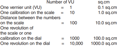
Figure 8: Vernier unit table
2)Environmental factors
External conditions are also important for the accuracy. Accurate results cannot be expected if the sheet or paper on which it is drawn is wrinkled or torn. Accurate temperature is 20o Centigrade or 68o Fahrenheit.
3)Human errors
Trained persons performs better than others that’s why concentration and patience plays key role while tracing. Day light and comfortable working position also effects results.
4)Size of the Area
Tracing a square with side length of 1 inch each with error of 0.01 inch externally, instead of 1 sq.in, value will be 1.04 sq.in = 4% error. If we repeat the mistake with square of sides 2 in each, result shows 4.08 sq.in = 2% error. The outcome for a 10 in. square will be 100.4 sq.in. = 0.4 % mistake. The bigger the area, the rate of mistake arises.