Table of Contents
Objective
The performance of this experiment targets the following objectives:
- To measure the volume flow rate or discharge through a pipe having a pressurized fluid flow
- To comprehend the abstraction of vena contracts in pipe flows
- To determine the coefficient of discharge of an orifice meter
Related Theory
Orifice:
An orifice is simply an aperture or hole and for flow measurement, it can be installed in a fluid tank (at the base or side) through which water is expelled out in the form of a jet.
Orifices are used to measure the discharge or volumetric rate of flow through tanks, reservoirs, or any fluid receptacle.
Evidently, the flow through an orifice depends upon the diameter and type of orifice as well as the head of fluid present above it.

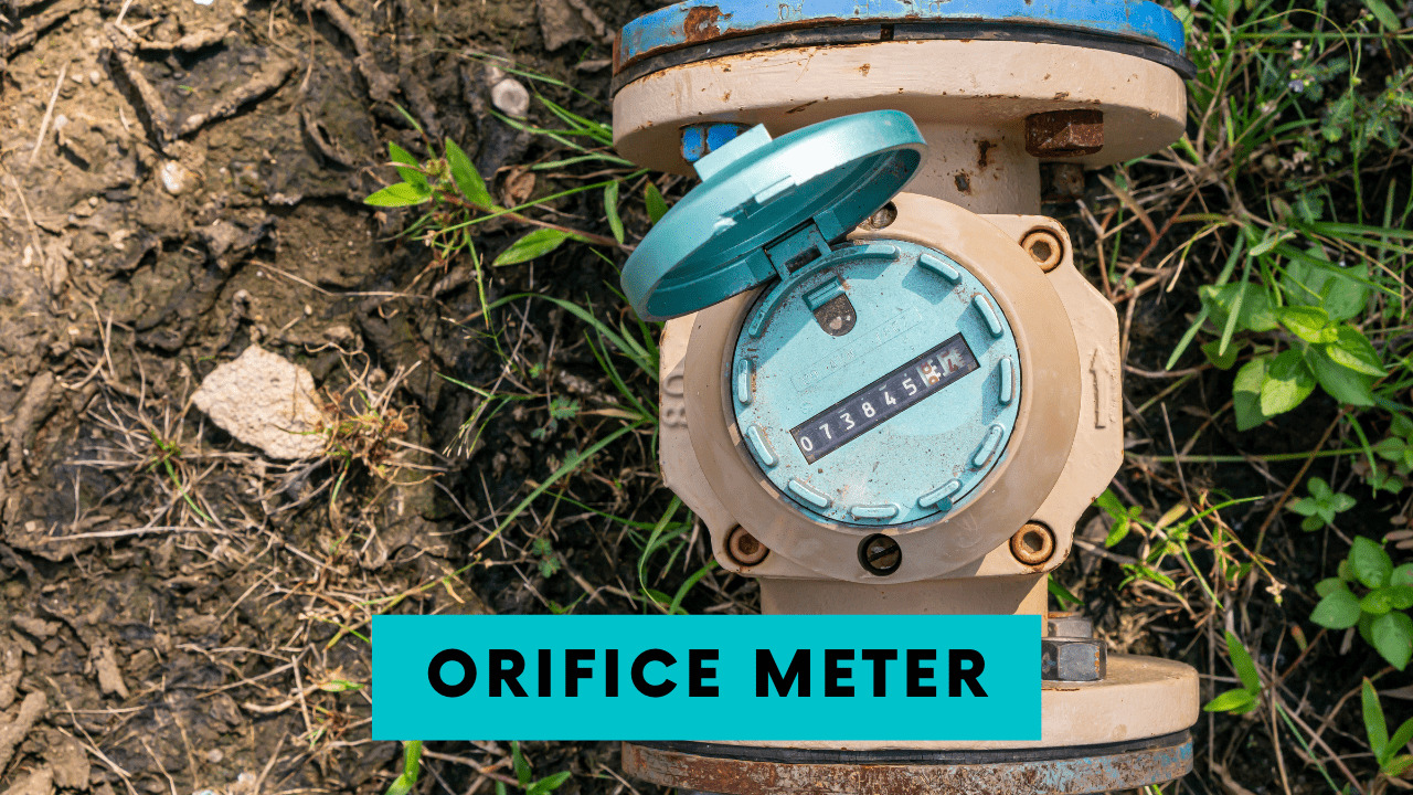
Orifice Meter:
An orifice meter or orifice plate is also a discharge measuring device employed in a pipe to create a pressure gradient by altering the pipe cross-section at the point it is installed. The differential pressure head is measured using a manometer and the discharge through the pipe cross-section can easily be calculated.
The figure above shows an orifice meter connected in a pipe of diameter D containing a fluid flowing under the influence of pressure forces.
Due to the presence of the orifice plate, the pipe’s diameter reduces. Consequently, the velocity of fluid shows an instantaneous surge, thereby dropping the fluid pressure at the contracted section.
The differential pressure becomes eminent on the limbs of the manometer in the form of a pressure step-down. The manometric fluid in both limbs of the manometer shows a difference in the levels which is noted down.


D =Diameter of pipe
A1 = Area of pipe at inlet
do = Diameter of orifice
A2 = Area of pipe at vena contracta
h = Pressure difference in the limbs of manometer
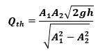
The theoretical discharge through the pipe cross-section can be calculated as;

The actual discharge can be determined by recording the time to fill a known volume of fluid in the volumetric tank.
Vena Contracta
When an orifice meter is installed in a pipe, the cross-section contracts. Consequently, the streamlines come close to each other. The section where the streamlines come the closest possible is termed the vena contracta. The velocity of fluid at this section shows an instantaneous hike followed by a pressure decrement.
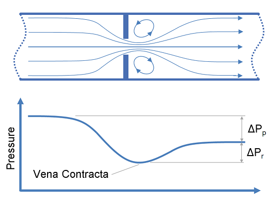
The figure above shows the graphical trend of pressure variation across the orifice plate. It can be seen that at the contracted section, the pressure magnitude is the least after which the pressure head is restored but to decremented value in comparison to the pressure at the inlet. This is because of frictional losses incurred as the fluid traverses the pipe length.
Coefficient of Discharge, Cd
The coefficient of discharge of an orifice meter is the ratio of the actual discharge to the theoretically-calculated volume flow rate. Mathematically, it is given as;

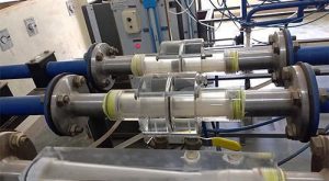
Apparatus
- Hydraulic bench, to measure the actual volume flow rate
- Stopwatch, to record the time taken to fill the tank to the required depth
- Orifice meter apparatus

Test Procedure
- Start the pump and by using the discharge control valve, adjust the flow rate and measure it by noting down the time taken (t) to fill the volumetric tank in the hydraulic bench to a known depth.
- Calculate the actual discharge as follows;
Q = V/t
- Before allowing the fluid to flow into the orifice meter apparatus, ensure that the pipelines are free from air bubbles. To do so, turn on the air-release valves to allow the air bubbles to traverse the pipe length to enter the tank.
- Open the valve of the orifice meter pipeline to allow water to flow through the orifice plate.
- The manometer present below shows a pressure drop. Record the level of manometric fluid in both limbs of the manometer in order to determine the differential pressure head.
- Calculate the theoretical discharge as follows;
- Determine the coefficient of discharge of the orifice meter by taking the ratio of actual discharge to the theoretical one.
- Repeat the above process for a different discharge value. To alter the flow rate, rotate the discharge control valve either clockwise or anticlockwise.
- Average out the value of the coefficient of discharge of the orifice meter.
Observations and Calculations
Inlet diameter of pipe = D =
Area of pipe at inlet = A1 = (π*D2)/4
Type of orifice plate used:
Diameter of orifice = do =
Area of orifice = A2 = (π*do2)/4
| Sr. No. | Level of manometric fluid (mm) | Differential Pressure Head, h (mm) | Volume
V (m3) |
Time
t (sec) |
Theoretical Discharge
Qth (cumecs) |
Actual Discharge
Qact (cumecs) |
Coefficient of Discharge
Cd |
|
| Left Limb | Right Limb | |||||||
| 1. | ||||||||
| 2. | ||||||||
| 3. | ||||||||
| 4. | ||||||||
Formulae Used:

Note:
The formula for calculating the differential head is based on the assumption that the flow through the pipe is from left to right such that the left limb of the manometer connected at the pipe inlet shows a higher value of pressure head than the right limb connected at the contracted section.
Results
Coefficient of Discharge of the orifice meter =
Precautions
- The availability of water in the sump tank should be ensured prior to pumping the water.
- The meniscus of the manometer should be read carefully.
- It is preferable to wear safety goggles and gloves while handling hydraulic fluids.
- It is imperative to remove the air bubbles in the pipelines that may otherwise yield misleading results.
Discussion
- The coefficient of discharge of an ideal pipe is 1. This is because the theoretical and actual flow rate values coincide. However, the existence of such a pipe is hypothetical and energy or frictional losses during the flow of fluid can be minimized but not eliminated.
- Depending upon the viscosity of the fluid and its Reynold number, different types of orifice plates can be used. These include segmental, eccentric, conical, and quadrant orifice plates.
- Orifice meters can serve to measure the discharge through water treatment plants, filtration plants, oil refineries, etc.