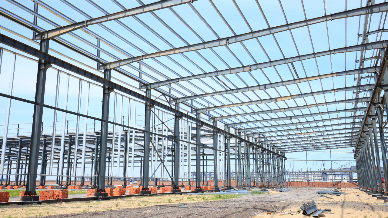
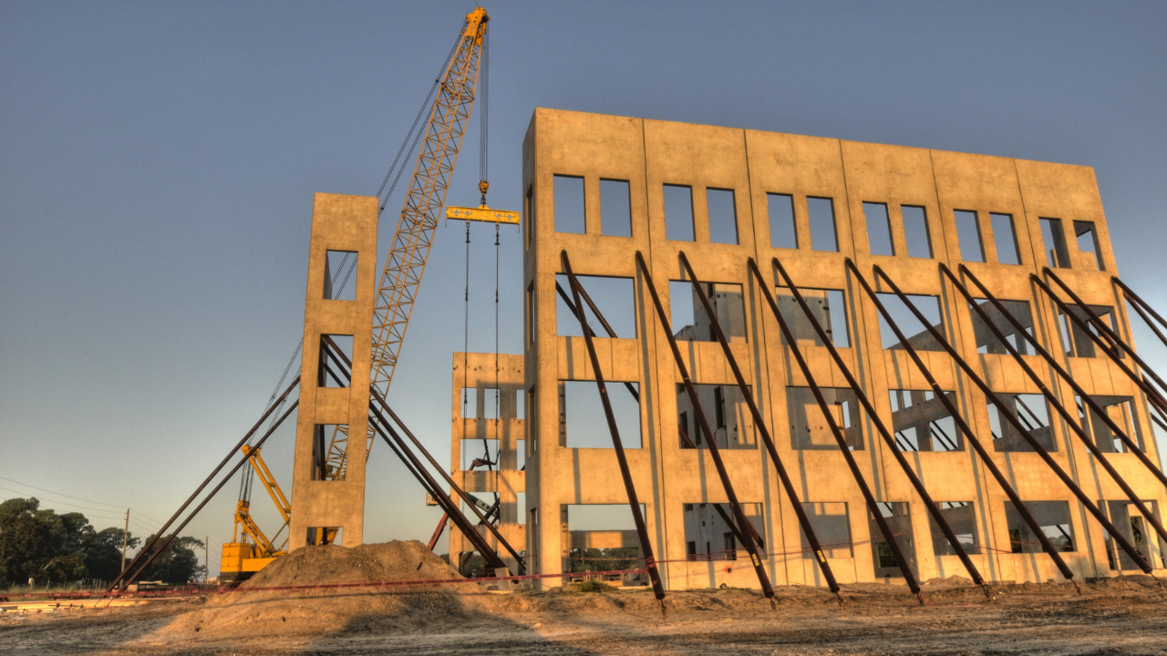
A frame is a structure composed of several members that are either fixed–or pin–connected at their ends.
It is often necessary to draw shear and moment diagrams to design frames
Procedure for analysis
The following is a procedure for constructing the shear and moment diagrams for a frame
- Determine the support reactions for the frame, if possible.
- Determine the support reactions A, V, and M at the end of each member using the method of sections.
- Construct both shear and moment diagrams just as before.
We will use the following sign convention: always draw the moment diagram on the compression side of the member.
Practical Example
Draw the shear and moment diagrams for the following frame:
First, find as many external reactions as possible.
Second, cut the frame into its component members and find the internal reactions
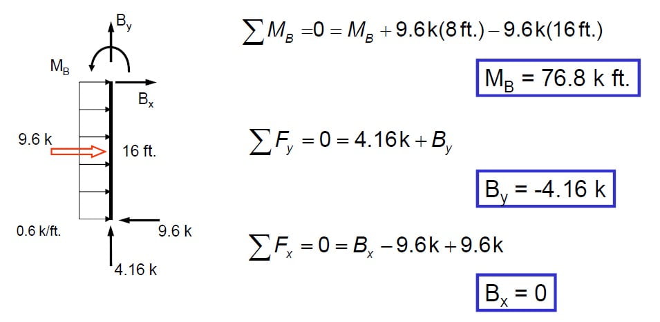
Next, solve the equations of equilibrium for each member. Let’s start with member AB.
Next, solve the equations of equilibrium for member CD.
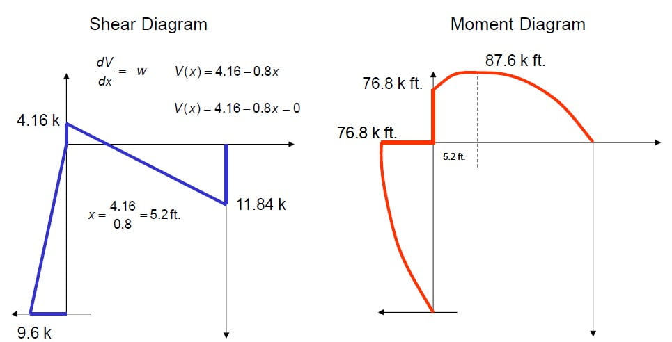
Now, let’s draw the shear and moment diagram (remember to draw the diagram on the compression side of the member).


