Table of Contents
Definition of contouring:
Contouring is the method used in surveying to determine the elevation of the points and to connect the points of equal elevation on the surface of the earth. That line that connects the points of equal elevation is known as the contour line. The contour lines are used to draw contour maps. These lines are the best way to represent the mountains, hills, valleys, peaks on a paper or drawing sheet.

Fig: Contour lines
Contour interval:
The distance between two successive contours vertically is known as contour interval.
The contour interval is dependent on many factors such as the scale of the contour map. The Contour interval should be a constant value. The purpose for which it is to be uses, time, and the type and nature of the surface of the ground. The contour interval and scale of the map are inversely proportional to each other.
Horizontal Equivalent:
The horizontal distance between two successive contours is known as the horizontal equivalent. The horizontal equivalent is a value that varies from point to point and is not constant. The steepness of the ground is the main factor that has a great effect on the value of horizontal equivalent. For example: If the ground is steeper, the horizontal equivalent will be less.
Contour Gradient:
A contour gradient is a line that shows the slope of the ground surface or terrain between two successive contour lines and can be ascending or descending. It is a line that maintains a constant slope throughout the horizontal ground surface. It can be represented by tanθ.
Contour gradient is shown in a format of 1 in S, here 1 is the vertical component and S is the horizontal component of a slope and both have the same units.
Some characteristics of contour lines:
- Any two contours of different elevations never intersect or cross each other except in the case of an overhang cliff or a cave.
- Ridge and contour lines always cross each other at the angle of 90 degrees means at the right angle.
- Widely spaced contour lines are the indication of a flat surface.
- The elevations of the contour lines are written or shown adjacent to the contour.
- Closely spaced contour lines are the indication of steep ground.
- Equally spaced contour lines are the indication of a uniform slope.
- Irregular contour lines are the indication of an uneven surface.
- Contour lines never pass-through permanent structures.
- Contours have soft and smooth turns and are not very sharp.
- A coastline is a zero-meter contour line.
- When contour lines are very close and higher values inside show a hill or peak.

Fig: Contour lines showing a hill
- When contour lines are very close and higher values towards the outside it shows a valley.

Fig: Contour lines showing a valley
Drawing of contour line:
- When the contour points are located then contour lines are drawn that connects those points by smooth and free hand curves.
- French curves can also be used to draw smooth curves.
- Drawing pen should be used while drawing the contour lines and should be black or dark brown in color for perfect visibility.
- Each elevation should be mentioned corresponding to each contour line.
- When the length of the contour line is very long then elevation should be written at more than one place.
- After drawing the four contour lines the fifth line should be thicker than other lines so that it is easy to read.
Methods used in locating the contour lines:
Contour lines can only be drawn if the elevations of selected points are known both horizontally and vertically. These elevations can be found out by following two methods:
- Direct method
- Indirect method
1)Direct Method:
In this method, the contour lines are traced and marked on the ground by locating the horizontal controls and vertical controls of the points which lie on these contour lines. This is an accurate method but time-consuming method.
This method is best for small areas. In finding the vertical control points the leveling instruments are used and all these points are according to a benchmark of known reduce level. If that benchmark is not present a temporary benchmark is considered.
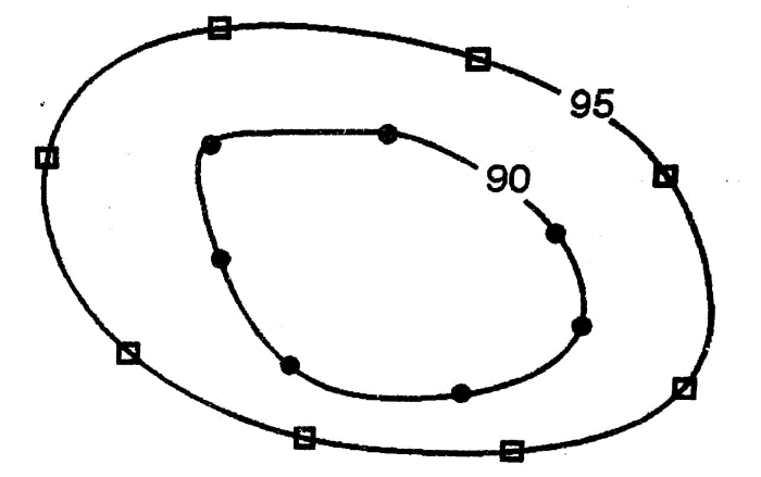
Fig: Contour lines drawn by direct method of contouring
2)Indirect method:
The indirect method requires a sufficient number of points and these points can be located with the help of a plane table and in the form of the geometrical shapes like triangles, squares, etc. and is further classified into three methods:
- Square method
- Cross-section method and
- Tachometric method
Detail of these methods:
i)Square method:
In the square method, the whole area is divided into different square patterns. These squares may have different sizes that are between 5m – 25 m. The elevation points are found out with the help of leveling instruments and the elevation of the corners of each square is found out. Then using the method of interpolation, the lines are drawn and this method is useful where the cross-section area is small. This method is also known as blocking contouring and co-ordinate method of locating contours.
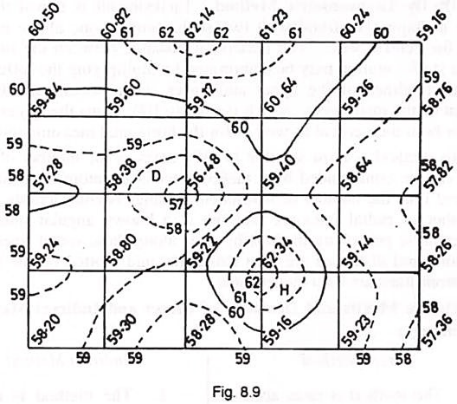
Fig: Contour lines drawn by square method of contouring
ii)Cross-section method:
In this method, the elevation of the points is found out with the help of leveling instruments at regular intervals and the same reference point is used in the whole procedure and then a contour map is drawn on the sheet. This method is useful in surveys of the canals, railway and highways or roads, etc.
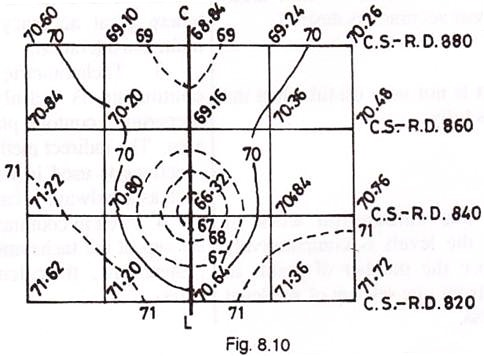
Fig: Contour lines drawn by Cross-section method of contouring
iii)Tachometric method:
This method is useful in hilly areas. The tachometer is the instrument that is used in this method. The tachometer is used to find out the elevation and horizontal distances between the points. Contour lines are drawn by the interpolation of the spot levels.

Fig: Contour lines drawn by tachometric method of contouring
Comparison between Direct and Indirect methods of contouring:
| Direct Method | Indirect Method |
| It is a costly method. | It is a method in which reasonable cost is required. |
| This method is very accurate but slow and tedious. | Not a very accurate method and is a fast and quick method. |
| This method is useful in case of low-lying areas. | This method is useful in case of mountainous and hilly areas. |
| The calculations cannot be rechecked once contouring has been done. | The calculations can be rechecked whenever and wherever required. |
| All the calculations are done in the field. | The calculation can be done both in offices and field. |
Methods used for interpolation of contours:
- Estimation method
- Arithmetic method
- Graphical method or mechanical method
Use of contours or contour lines:
As we already know that contour lines are used to draw the contours maps and there are many uses of these maps that are described below:
- It is used to study the ground characteristics without visiting the site and plays a very important role in understanding the structure of the site.
- A contour map is used for the alignment of roads, railway lines, and canals.
- Contour map helps in finding the catchment area of river and ponds etc.
- It is used for the calculation of the capacities of the reservoirs.
- It is also used for the computation of the earthwork i.e., cutting, filling, etc.
- Contour maps can help in different projects regarding the economic cost and suitable site. For example, best place for the construction of a dam.
- Contour maps help in identifying the difference in elevation of the existing land.