In this type of survey, graphs are plotted using those observations that are made in the field, plotting of graph is done just after noting those observations. Plane table survey is done on a small scale and is simpler than other advanced techniques of surveys like theodolite surveying.

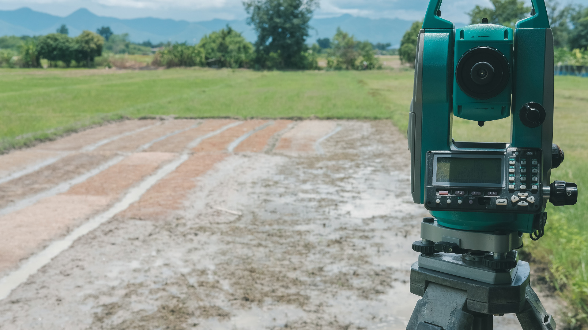
Fig: Plane Table Surveying
Table of Contents
Parts
In-plane table surveying many types of equipment are used that are listed below:
- Plane table
- Compass
- Spirit level
- Alidade
- Tripod stand
- Plummet
- Drawing sheet
- Umbrella
- Drawing tools i.e., pencil, eraser
Details of essential equipment:
1)A Drawing board
It is attached to a tripod stand and levelling of the table can be done by moving its legs or using screws (foot screws). The drawing board is attached to the equipment in such a way that it can be revolved around the y-axis or vertical axis and we can change its direction according to our requirements.
2)Alidade
It is a straight edge tool. It can be plain or telescopic. It is used to bisect the lines, objects, and other things.
3)Umbrella
It is used in case of rain to avoid any moisture on the drawing paper.
4)A Plumb bob
It is used to center the instrument and when the scale of the work is big.
5)Spirit level
It is used for levelling. Its function is to level the table surface in perpendicular directions.
6)The Compass
It tells us about the poles and their direction and is used in the orientation of the plane table.
7)The plummet
It is used in the centering procedure.
Plane table setting:
The setting of the plane table consists of three steps mainly in this the first step is to centre the plane table, in the second step the plane table is levelled, and in the third step the alignment of the plane table is done according to the lines on the ground and this can be done by using and adjusting the legs of the stand and screws.
Methods used in plane table survey:
There are four methods that can be used in plane table surveying.
- Resection
- Traversing
- Radiation
- Intersection
Detail:
1)Resection method,
In this method two points are used and by using these two points the third unknown point is determined. This method is also known as free stationing because the instrument can be freely transferred from one point to the other in the field or from one station to the other.
Its main use is to draw the station or point that is under the equipment of the plane table. This method is further classified into these categories:
- Two-point method
- Three-point method
- Back sighting method
- Trough compass method

Fig: Resection Method, Source: N.N. Basak, Surveying, and Levelling
2)Traversing method,
In this method the connection between different stations is made, and the traverse can be open, or the traverse can be closed also and the number of lines may be present on the sheet. The traversing method is used to locate the details of the topography and it is done the points where the station has been already fixed.

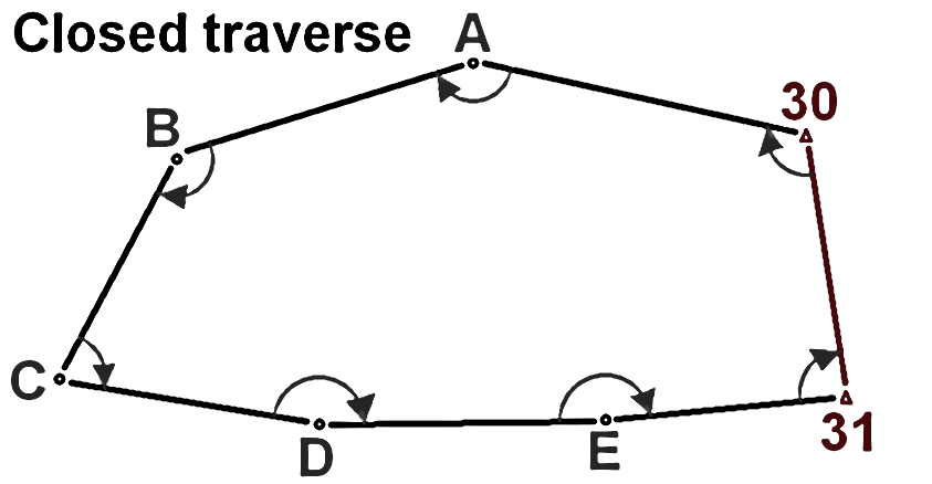
Fig: Traverse Method (Open traverse on left, Close traverse on right)
3)Radiation method,
In this method the equipment is set on only one point at any place in the field and from that point, a complete traverse can be ordered and arranged. In this method, the plane table is placed in such a manner that all the points can be surveyed from that one point.
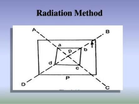
Fig: Radiation Method
4) The Intersection method
It is also known as triangulation in this method the equipment is set on the two-station minimum and then the whole field to be surveyed can be commanded, and it can be done only by the orientation by the back sighting.
This method is usually used in areas where the terrain is mountainous and irregular. This method is best for those areas where it is not possible to go and take individual readings so that point can be found out by this method.

Fig: Intersection Method
Uses
- This technique is used to draw drawings, charts, and maps.
- This type of survey is used in the areas where the magnetic field is strong.
- It is a less costly method that’s why can be easily accessible.
- It is used to calculate and measure the length of lines and the angles in the field.
- Gives accuracy for the small areas only.
Precautions
- The equipment should be leveled and centered properly.
- Sighting of the points should be accurate.
- The drawing sheet must be horizontal.
- The lines drawn on the drawing sheet should be drawn as fine and smooth as possible so that there should be no difficulty and error later on.
- Always carry an umbrella with you to avoid the wetting of the drawing sheet due to rain.
Errors:
Errors maybe
- Instrumental error
- Human error (Due to false manipulation and sighting and plotting the points)
Detail:
Instrumental errors
Errors that are caused by the apparatus if the apparatus is not in its best working condition.
- If the surface of the drawing board is not perfectly straight and smooth there are chances of error that the lines are not drawn straight.
- If the edges of the alidad are not straight and its sights are not perpendicular to its base it also hinders the drawing of straight lines.
- If the compass is defective, it causes a lot of trouble in guessing the direction and in lane table orientation.
- If the screws and the legs of the stand are loosed it causes the movement of the equipment after the setting of the plane table
- If the quality of the drawing paper is not up to the mark
Human errors
(Due to false manipulation and sighting and plotting the points). These are the errors caused by the human if he/she is not experienced or not paying attention to the work.
- If the board is not placed perfectly horizontal it causes problems while drawing and plotting the points.
- If the orientation of the equipment is not done properly it causes trouble.
- If the alidad is not centered correctly on the station it causes irregular lines that are not according to the station point that is drawn on the sheet.
- If the plane table is not clamped by the person tightly it causes movement of the table after its setting has been done.
- If the drawing on the paper is not proper and has flaws on it like thick lines then it is difficult to understand the sheet and points.
- If the scale is not used by the person who is drawing this causes the error.
Pros and cons
- It does not require a separate notebook to note down the values that’s why chances of error while noting down are not there.
- As the plotting is done at the same time so chances of error in calculations and drawing are very less
- It is a fast method and useful method for noting details.
- Cannot be used in moist weather because it affects the drawing sheet.
- The equipment is heavyweight and is difficult to move.
- We have to level and center the equipment when moved from one station to another which is sometimes very hectic and tiring.