Table of Contents
Statement:
To determine tension and compression in the members of a jib crane
Apparatus:
- Jib crane
- Weights
- Measuring scale
- Weight hangers
Theory:
Cranes are used to lift heavy weights. Cranes form an important part of the civil engineering projects. Different kinds of cranes are utilized depending upon weight to be lifted and available area for movement. One such type is the jib crane.
A jib crane is a type of crane that utilizes a mounted arm in lifting, moving and lowering materials. The fundamental idea of a crane stems from the mechanical advantage concept (The ratio of the loads’ weight to the applied force is equal to the ratio of the lengths of the longer arm and the shorter arm). Mechanical advantage refers to the principle that a machine, like a pulley is capable of multiplying the force exerted on it by a given factor. Jib crane could be free standing, wall mounted or wall bracket.

Procedure
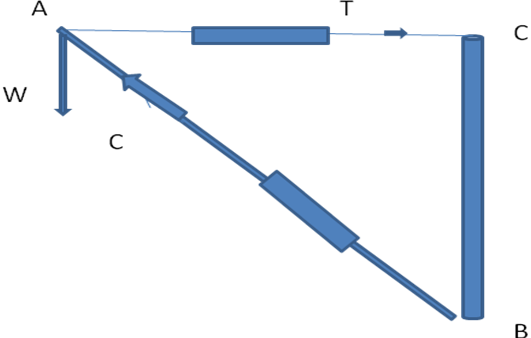
The jib crane in our lab consists of a vertical post fixed with the wall, a tie arm and a jib arm. Spring balances are attached with the tie member and jib arm. The equipment is considered to be frictionless. A load W is suspended from the toe of the jib. When load W is suspended, the tie member gets elongated and hence it is in tension, while jib arm gets compressed and hence it is in tension. Point A is in equilibrium. Now utilizing the geometrical properties, we can calculate the forces in tie and jib member.
- Measure the length of the post, tie member and jib
- Length of the jib is variable, so measure it in two portions (fixed and variable)
- Let us assume that forces in tie arm and jib are “ T” and “ C” respectively and note them down from the spring balances
- Hang a weight W at the toe of jib, and is assumed to be correct whereas T and C may not be correct.
- Let us assume that “T’” and “ C’” are the correct values of forces in tie and jib arm respectively
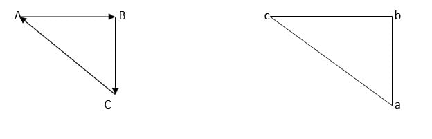
- Make a triangle abc as shown below in the diagram and calculate correct values of forces in the tie arm and jib
- Since the triangle abc and ABC are similar (all angles same)
- Therefore,
- T’/AC = C’/AB = W/BC
- It can be assumed that lengths are measured correctly
- Compare the value of T’ and C’ with T and C and apply correction
- % Error = (T-T’/T’)100
- Take five sets of reading by changing weight W and tabulate the results
Tabulation of Data:
| Sr no | Weight W | Tie Arm Length | Jib Arm Length | Tension | Compression | ||||
| T | T’ | Error | C | C’ | Error | ||||
| 1 | |||||||||
| 2 | |||||||||
| 3 | |||||||||
| 4 | |||||||||
| 5 | |||||||||