Table of Contents
List of Appurtenances
- Manholes
- Clean out
- Street inlet
- Flushing tanks
- Grease & Oil traps
- Storm water regulator
- (Inverted) siphons
- Pumping stations
- Septic
- Other appurtenances Lamp holes and sewer ventilators
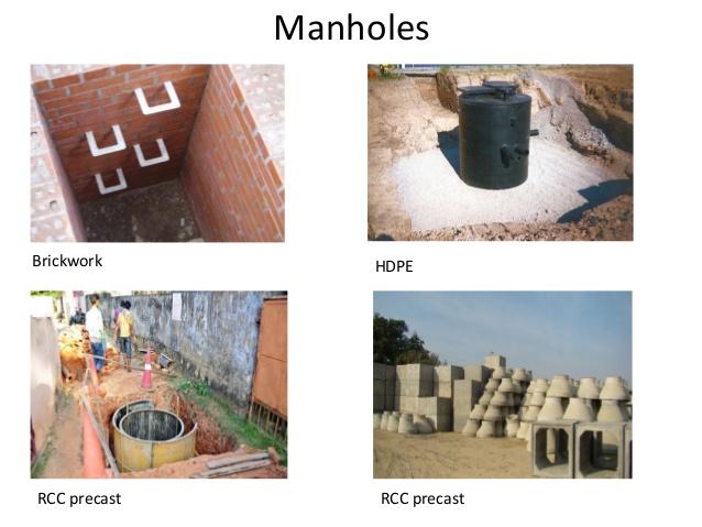
1) Manholes
The manhole is masonry or R.C.C. chamber constructed at suitable intervals along the sewer lines, for providing access into them. Thus, the manhole helps in inspection, cleaning and maintenance of sewer. These are provided at every bend, junction, change of gradient or change of diameter of the sewer. The sewer line between the two manholes is laid straight with even gradient. For straight sewer line manholes are provided at regular interval depending upon the diameter of the sewer.
For sewer up to 0.3 m diameter or sewers which cannot be entered for cleaning or inspection the maximum spacing between the manholes recommended is 30 m, and 300 m spacing for pipe greater than 2.0 m diameter A spacing allowance of 100 m per 1 m diameter of sewer is a general rule in case of very large sewers (CPHEEO, 1993). The minimum width of the manhole should not be less than internal diameter of the sewer pipe plus 150 mm benching on both the sides.
| Pipe diameter | Spacing |
| Small sewers | 45m |
| 0.9 to 1.5 m | 90 to 150 m |
| 1.5 to 2.0 m | 150 to 200 m |
| Greater than 2.0 m | 300m |
| Depth of sewer | Internal dimensions |
| 0.9 m or less depth | 0.90 m x 0.80 m |
| For depth between 0.9 m and 2.5 m | 1.20 m x 0.90 m, 1.2 m dia. for circular |
| For depth above 2.5 m and up to 9.0
m |
For circular chamber 1.5 m dia. |
| For depth above 9.0 m and up to
14.0 m |
For circular chamber 1.8 m dia. |
Classification -Materials
Depending upon the depth the manholes can be classified as:
- Shallow Manholes,
- Normal Manholes,
- Deep Manholes
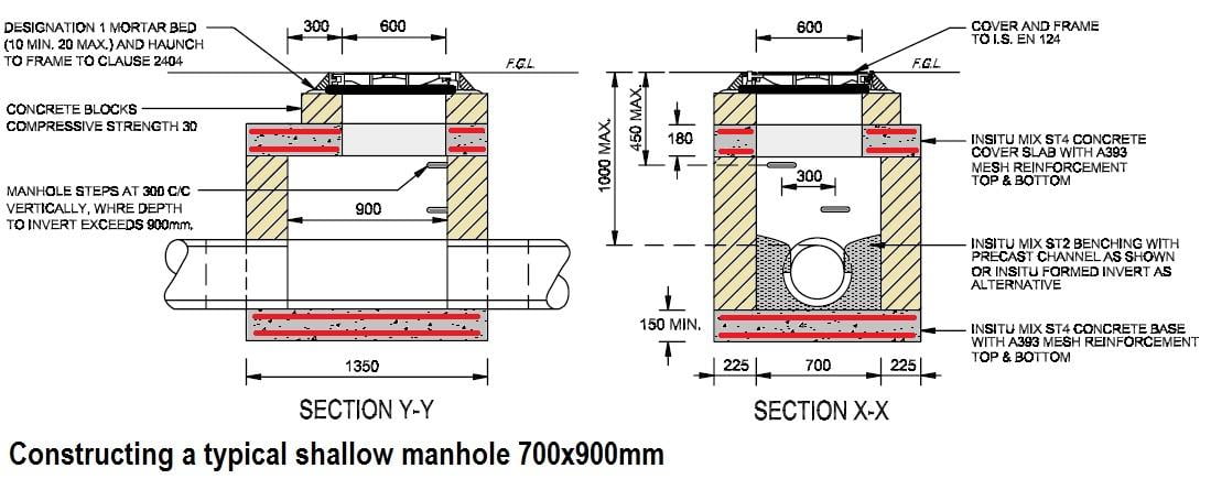
a) Shallow Manholes:
These are 0.7 to 0.9 m (2ft to 3 ft) depth, constructed at the start of the branch sewer or at a place not subjected to heavy traffic conditions. These are provided with light cover at top and called inspection chamber.
b) Normal Manholes
- These manholes are 1.5 m deep with dimensions 1.0 m x 1.0 m square or rectangular with 1.2 m x 0.9 m.
- These are provided with heavy cover at its top to support the anticipated traffic load.
c) Deep Manholes
- The depth of these manholes is more than 1.5 m. The section of such manhole is not uniform throughout.
- The size in upper portion is reduced by providing an offset. Steps are provided in such manholes for descending into the manhole. These are provided with heavy cover at its top to support the traffic load.
d) Flushing Manholes
In flat ground for branch sewers, when it is not possible to obtain self cleansing velocity at all flows, due to very little flow, it is necessary to incorporate flushing device. This is achieved by making grooves at intervals of 45 to 50 m in the main drains in which wooden planks are inserted and water is allowed to head up. When the planks are removed, the water will rush with high velocity facilitating cleaning of the sewers.
Alternatively, flushing can be carried out by using water from overhead water tank through pipes and flushing hydrants or through fire hydrants or tankers and hose.
Flushing manholes are provided at the head of the sewers. Sufficient velocity shall be imparted in the sewer to wash away the deposited solids.
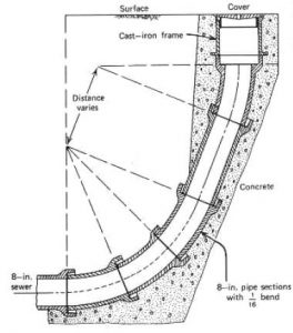
e) Drop Manhole
- The manhole, in which a vertical pipe, is used is called a drop manhole.
- When a branch sewer enters a manhole by more than 0.50m to 0.60m above the main sewer.
- The sewage is generally not allowed to fall into the manhole.
- The sewage is brought into it through a down pipe taken from the branch sewer to the bottom of the manhole.
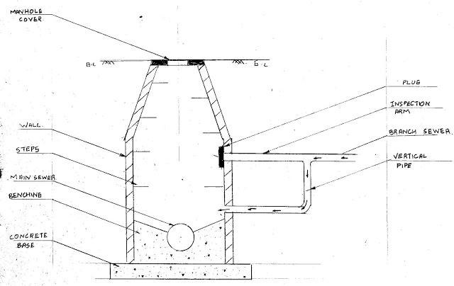
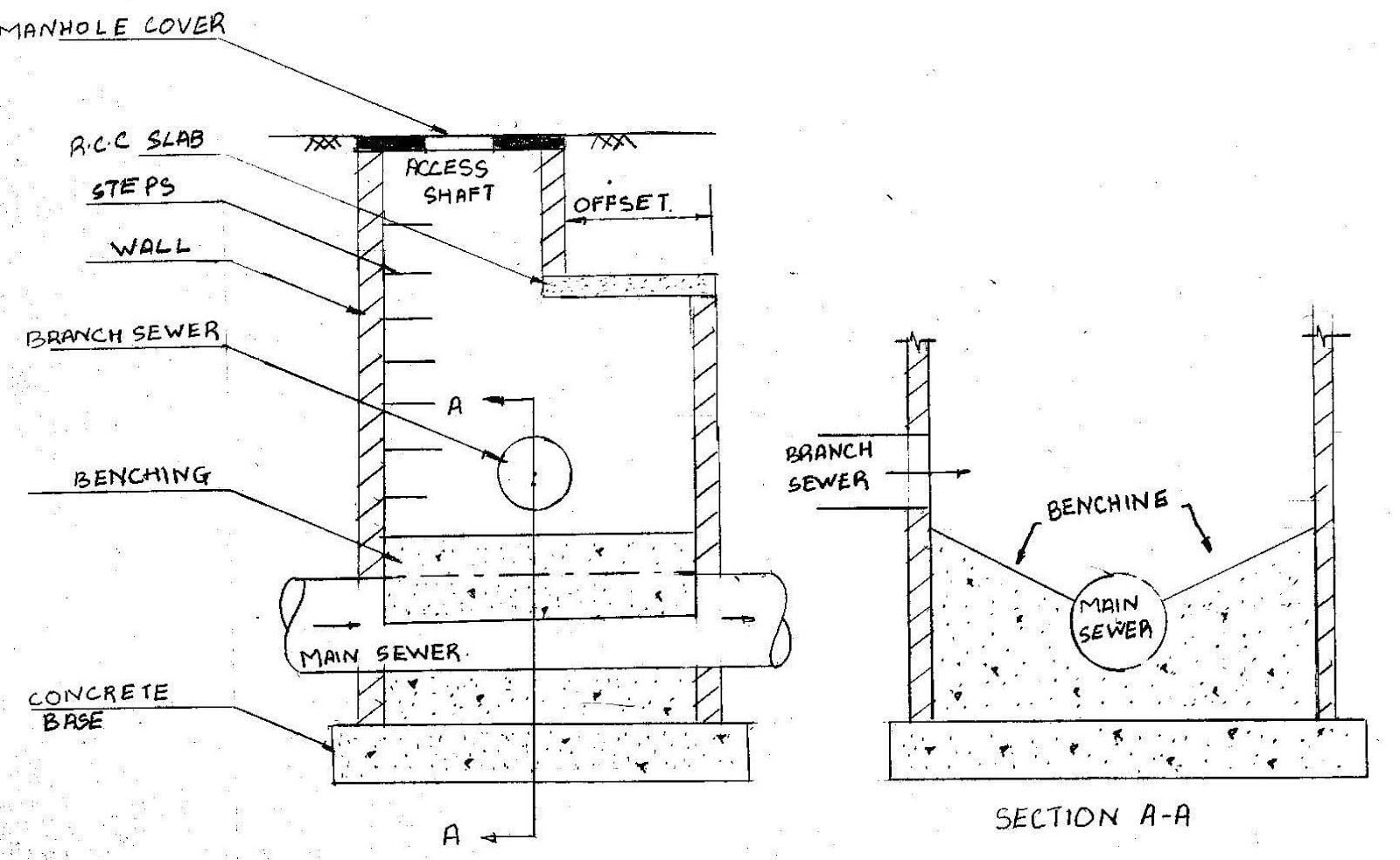
Components of Manhole
- Manhole cover and Frame: A manhole is provided with a frame on top which ic embedded in the pavement. A cover is provided on the top of frame.
- Access shaft: The portion of manhole starting from cover and going towards the full dia of manhole is called access shaft, which is in the shape of a cone.
- Walls (Side walls): The side walls of manholes are made of bricks, stones or RCC.
- Working chamber: The lower portion of manhole with vertical walls is known as working chamber, as it provides a working space for inspection and cleaning operations.
- Steps or ladder: Steps are provided for descending into the manhole. Steps are made of cast iron.
The benching i.e the botton: - The bottom portion of the manhole is constructed in cement concrete. A semicircular or a u shaped channel is generally constructed and the sides are made to slope towards it.
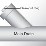
2) Cleanouts
- An inclined pipe connected from above ground to the sewer
- Provided at the upper ends of the lateral sewers in place of manholes
- When needed, cover of the cleanout is removed and water is forced through for cleaning the sewer
- If needed a flexible rod is inserted for removing the obstructions
3) Street Inlets
Inlets are openings on the road surface at the lowest point for draining rain water from the roads and admitting it into the under ground storm water sewers.
There are two types of street inlets viz.
- Vertical Inlet
- Horizontal Inlet


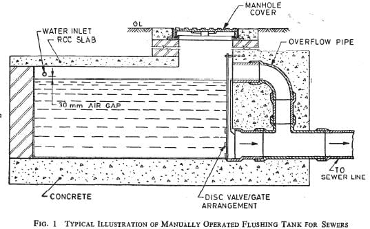
4) Flushing Tanks
- It is provided when there are chances of blockage.
- When the self cleansing velocity of the sewer is very less or when the pipe is laid straight.
- It is also placed at dead end points of sewer.
- These devices store water temporarily, and
- Throw it into the sewer for the purpose of flushing and cleaning the sewer.
- Types of flushing operations are
- Hand Operated Flushing Tank(manual)
- Automatic Flushing Tank
Manual Flushing Tank
Automatic Flushing Tank
- The flushing operation is carried out automatic at regular intervals.
- The entry of water is so regulated as to fill the tank upto the discharge point in a period equal to the flushing interval.
- An overflow pipe is also provided to drain away water in case the tank fails to discharge and thereby overflow.
| Sewer diameter
mm |
Sewer length
(m) |
Flush water need |
| 250 | 75 – 90 | 1.4 – 1.7 m3 |
| 350 | 75 – 90 | 1.7 – 2.7 m3 |
| 400 | 75 – 90 | 2.7 – 3.6 m3 |
| 450 | 75 – 90 | 3.6 – 4.5 m3 |
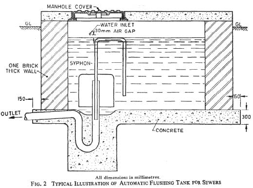
Automatic Flushing Tanks
- A masonry/concrete/RCC flushing tank has an Adam’s siphon (automatic siphon) at the bottom
- Adam’s siphon is in cast iron and comes in different diameters (65, 80, 100 mm diameter)
- The jointing should be leak proof
- The tank has a water supply connection
- A physical break (of 30 mm) between the water supply connection and maximum water level in flushing tank is ensured
- When the tank is full, the siphon goes into operation and water is quickly discharged into the sewer
The flushing frequency should be once a day
5) GREASE AND OIL TRAPS
- Grease and oil traps are those trap chambers which are constructed in a sewerage system to remove grease and oil from the sewage before it enters into the sewer line.
- Such traps are located near the sources contributing grease and oil to the sewage.
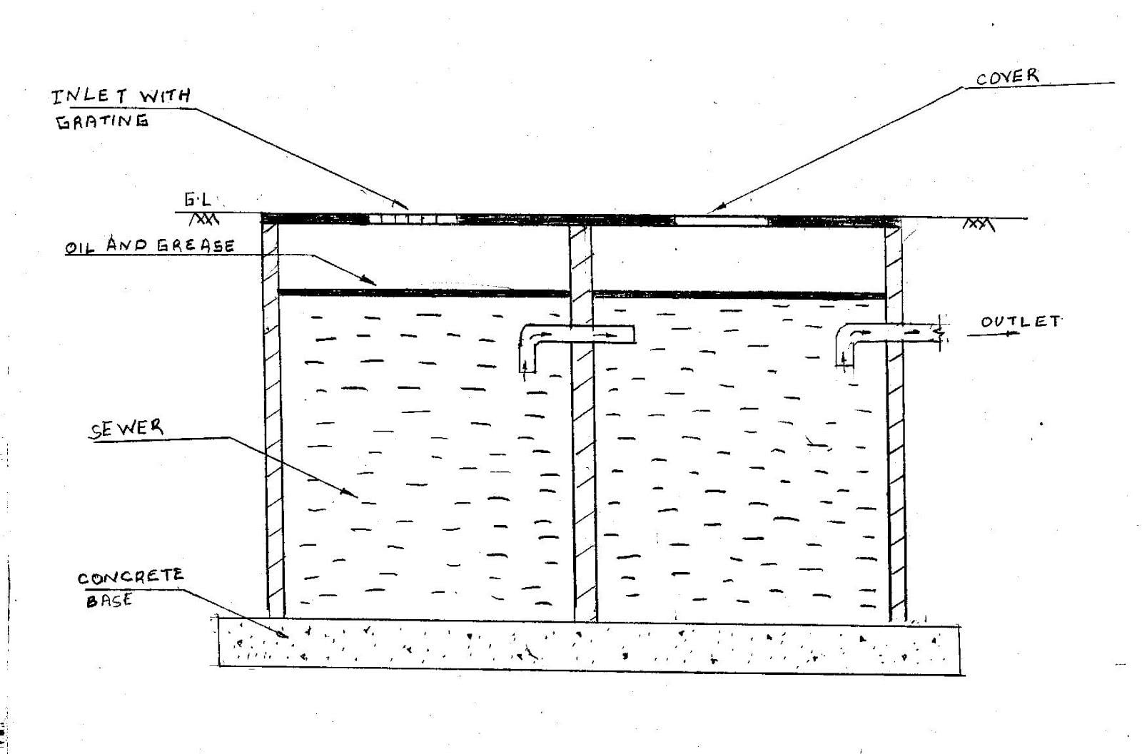
Sand Traps
If sand is also desired to be excluded from the sewage, dead space should be kept at the bottom of the chamber for sand to be deposited.
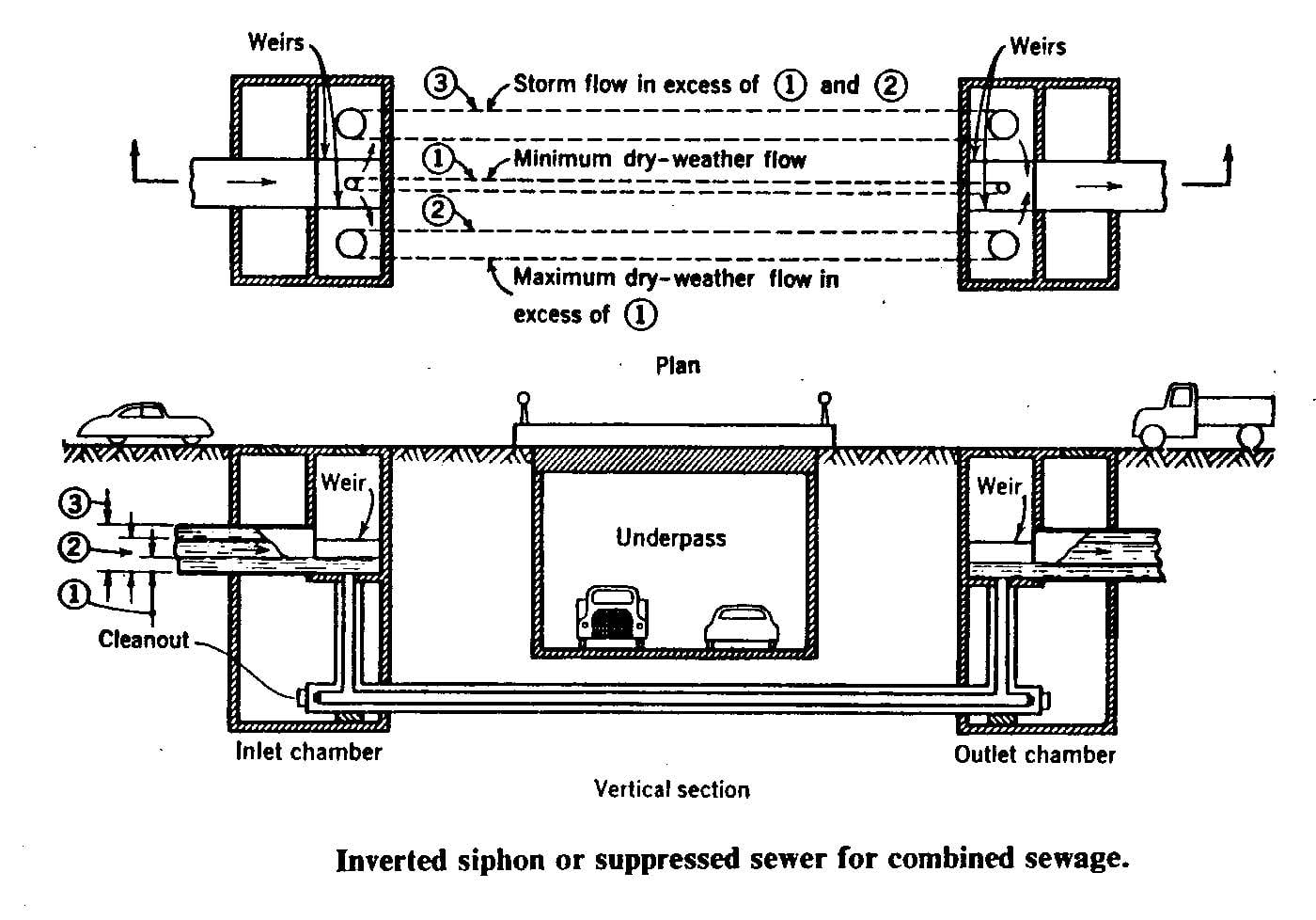
6) Inverted Siphons
- It is the section of a sewer at a lower elevation than the adjacent sewer
- It is actually a depressed sewer or a sag pipe used to carry sewage below obstructions (ground depressions, streams, rivers, railway lines, etc.)
- These pipes flow full under the pressure greater than the atmospheric pressure
- Inverted siphon usually includes two or more pipes of ≥200 mm diameter running parallel
◦1st pipe carries dry weather minimum flow
◦2nd pipe carries the difference of dry weather minimum flow and dry weather maximum flow
◦3rd carries the storm water flow
◦Large fluctuations in storm water flows demand >3 pipes - Minimum dry weather flow, maximum dry weather flow, and maximum wet weather flow for the design period are required for the design of inverted siphons
- Flow velocity in the siphons is maintained at ≥1.2 m/sec. for self cleansing
◦Velocity produced in the siphon pipe is function of the liquid level difference between the siphon’s inlet and the outlet - Deposits are prone to form at siphon pipe bends
◦Sharp bends are avoided and only easy bends are allowed - Provisions to isolate any of the siphon pipes for cleaning
◦Suitable penstocks or stop planks are provided at both the inlet and outlet ends for this purpose - Siphon pipes under river beds are
◦Surrounded by RCC of appropriate thickness to prevent floating when empty
◦Protected against the water currents - Outlet chamber is designed to prevent backflow of sewage
Inverted siphons are constructed of cast iron pipes or reinforced pressure pipes
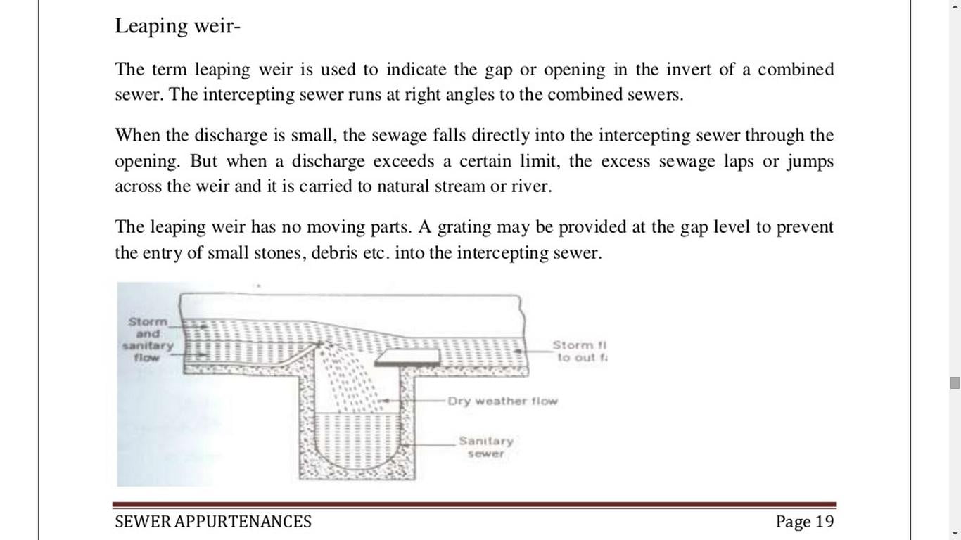
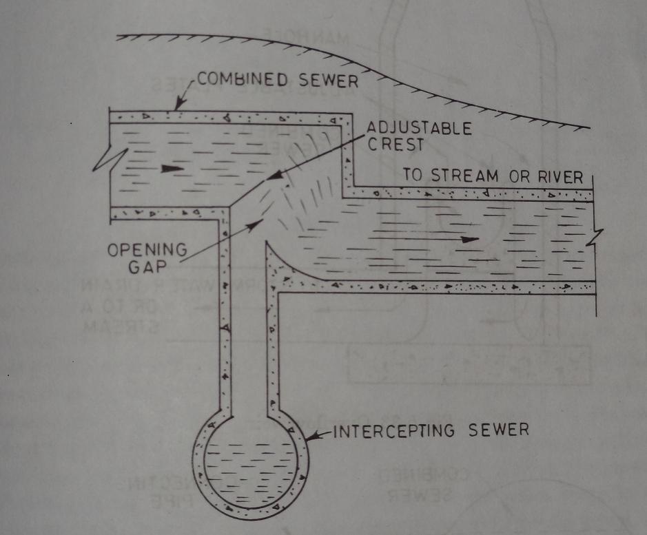
7) STORM WATER REGULATOR
They are constructed in the combined sewerage systems, and permit the diversion of excess storm water into a nearby stream.
Storm water regulators may of the following types:
- Leaping Weir
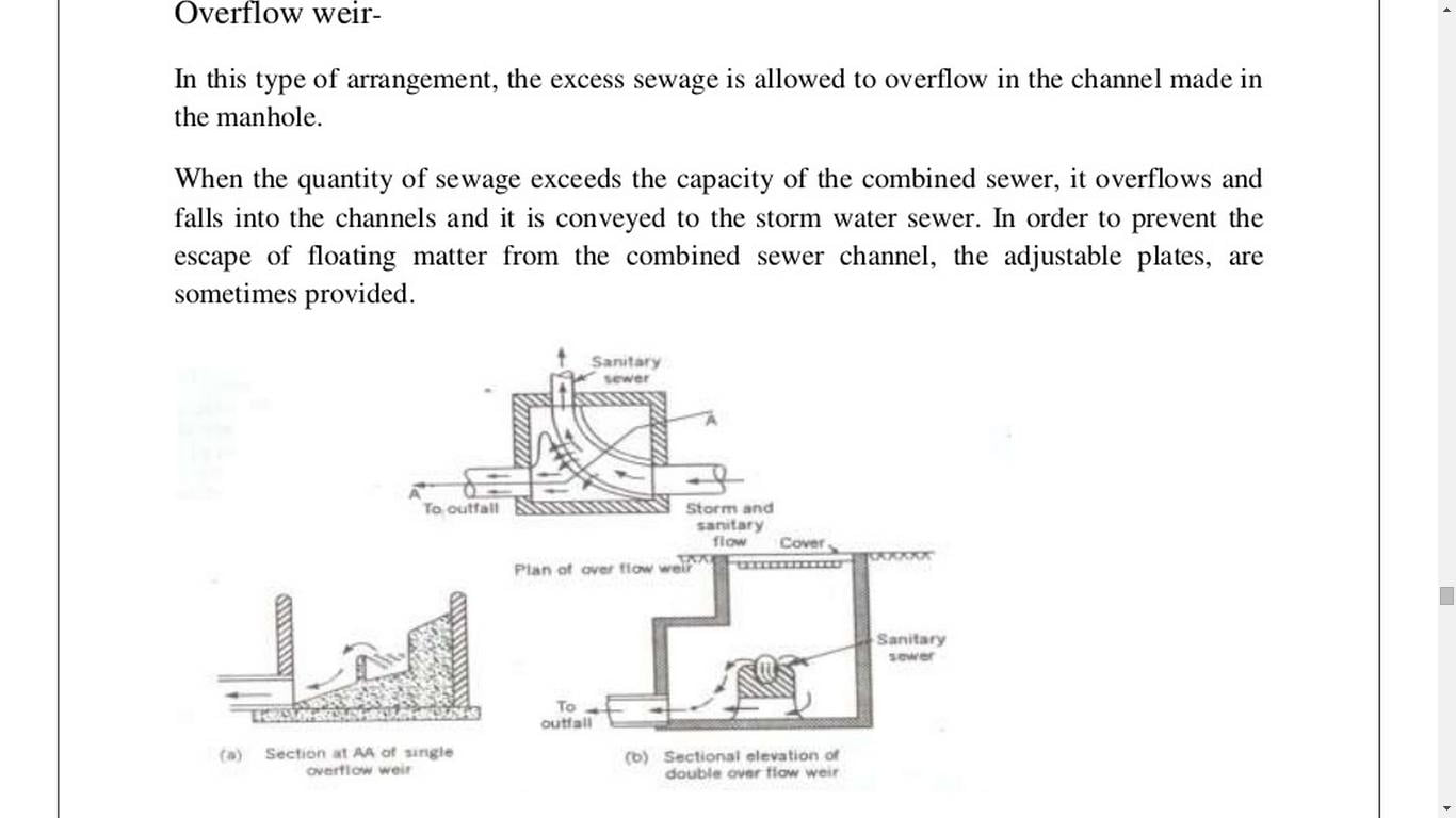
- Overflow Weir
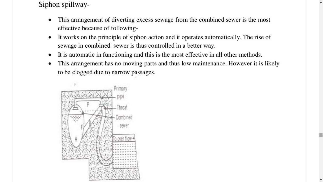
- Siphon Spillway
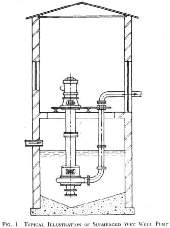
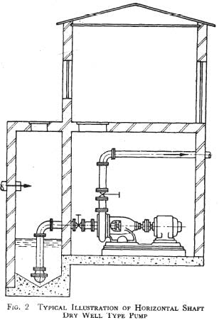
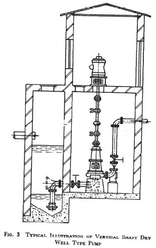
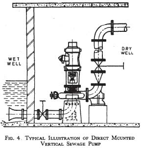
8) Sewage Pumping Stations
Sewage is required to be lifted from a lower level to a higher level at various places in a sewerage system. The building where pumps and other accessories are installed for lifting sewage is called sewage pumping station.
a) Need of pumping:
Pumping of sewage is required if
- Natural slope is not available for transport of sewage by gravity flow.
- There is some obstruction in passage of sewage flow.
- The receiving stream for sewage is higher than sewage outlet
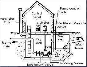
b) Components of pumping station
- Bar screen
- Wet well /sump well
- Dry well/sump room
- Motor room
- Other appurtenances
Described as follow
- Bar Screens: Sewage usually contains floating materials which must be removed prior to pumping as they are dangerous to the pumps. This is done by bar screen at the inlet of the wet well.
- Wet well: The purpose of wet well is to form a suction pit from which the pump may draw sewage through the suction pipe. It may be square, rectangular or circular in shape and is made of concrete or masonry. The wall at the inlet is made sloping to prevent accumulation of solids. A manhole is provided at the top. A standby unit is often provided which is interconnected by gates for cleaning and maintenance.
- Dry well: It is provided for the installation of pumps and situated at the side of wet well. It may accomodate a workshop and space for future work. Motor may be provided here.
- Motor room: This room is situated above the pump room and accomodates the electric motor which drives the pumps. Some appurtenances are also installed here.
- Other
c) Pumping stations for water and wastewater
Traditional pumping stations had both wet well and dry well
◦Smaller foot print, availability of submersible non-clog pumps, reduced health and safety concerns
- Designed to handle both normal and peak flows
◦Redundancy is built into the system - Capacity of the wet well is designed such that
◦pump starts and stops are minimized
◦sewage in the sump will not become septic - Have level switches in the sump to turn on or turn off the pumps
◦Level switches may also be provided in the receiving reservoir/overhead tank - Settling of solids and accumulation of grit in the wet well is avoided by design
◦Screens and grit channels/chambers are provided up stream - Sewage can enter the dry well from failures and leaks of pumps and seepages from wet well
◦Electrical motors mounted above the top sewage level in the wet well with extended vertical shafts are often used
◦Separate pump of appropriate capacity and head are often provided to take care of the seepage - Dry well usually designed to allow removal of pumps and other equipment from outside the wet well
◦Poisonous gases can accumulate in the wet well and human entry into wet well may require correct confined space entry methods
d) Sewage Pumps
- Pumping stations should deal with
- Both daily and seasonal flow variations
- Both dry weather and wet weather flows – whether the sewage is sanitary, storm or combined matters
- Number of and size of pumps should be chosen on the basis of
- Overall economy of pumping
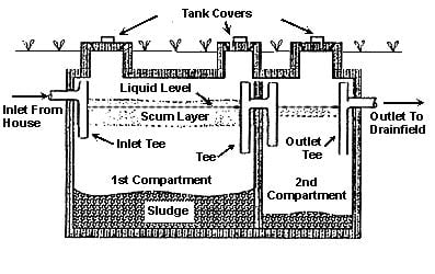
9) Septic tank
- Septic tank is an on-site sewage treatment unit
- Clarification (separation of both settlable solids and floating materials) of raw sewage occurs
- TSS, BOD and oil & grease are removed by 60-80%, 50-60% and <80% efficiencies respectively
- Digestion or stabilization and storage of the settled sludge till pumped out once in 3 to 5 years for cleaning
- Removal of nutrients, pathogens and metals also occur
- Conditioning of sewage for further treatment and equalization also occurs
- Located in open to sky areas and should be accessible for cleaning
- Should not be located in swamp areas and not in areas prone to flooding
- Usually rectangular tanks with 2 to 4 aspect ratio
- Minimum width is 750 mm, maximum depth is 1000 mm and minimum capacity is 1000 L
- HRT is 24 to 48 hours for average daily flow
- Septic tank is compartmentalized (has two or more compartments) when size is >2000L
- 1st chamber is twice the size of the second chamber
- The two chambers are connected by 100-150 mm size openings at 300 mm below the top water level
- Duplicate septic tanks are used when the serving population is >100 (to facilitate desludging)
- Inlet introduces raw sewage into the septic tank without disturbing the settled sludge and the floating scum
- Outlet withdraws sub-surface clarified sewage from septic tank without disturbing the settled sludge and the floating scum, while maintaining constant water level within
- Contains a bottom settled sludge zone, a middle clear wastewater zone and a top floating scum zone
- Has manholes one per chamber of 455×600 mm size rectangular manholes or 500 mm size circular manholes
- Vent pipe of 50 mm size and >2 m height

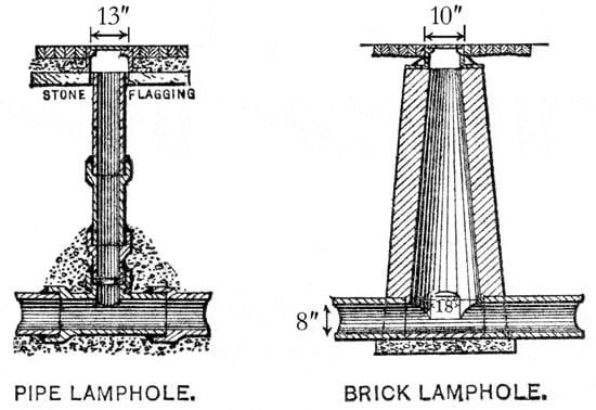
10) Lamp holes
- Lamp holes are the small openings on sewers to permit the insertion of a lamp into a sewer.
- The lamp light is then viewed from the upstream as well as the downstream manholes.
- The obstructed light confirms the obstructions in the sewers.