Table of Contents
Water Supply and Distribution
Introduction

After having treated raw water in water and wastewater treatment plants, the last and final stage of water supply scheme is distribution of water to consumers. The distribution system is a network of pipe lines inside the municipal limit, for transporting purified water to the consumers.
The distribution system consists of large sized mains, arterial mains and minor distributors.
Requirements of distribution systems
- During transmission of purified water to consumers from water treatment plant, degree of purity should be maintained. This requires the water supply system to be water-tight.
- Water head at the consumer tap should be sufficient. Larger pressure requires smaller diameter pipe and vice versa. Also, head should not be so excessive that is bursts pipes and fittings.
- Ample quantity of water should be available for domestic, industrial and other purposes.
- Maintenances of the distribution system should be easy and economical.
- During emergency periods such as fire breakout, it should be able to supply sufficient amount of water.
- Water should remain available even during breakdown periods of a pipeline. System of distribution should not be such that if one pipe bursts, it renders a large area without water.
- Repair and maintenance work should not disrupt traffic. In other words, the pipeline should not be under highway carriages but below footpaths.
Distribution systems
The main purpose of the distribution system is to develop adequate water pressure at consumer tap.
The choice of distribution system depends on topography of area of distribution, elevation with respect to location of WTP.
The distribution system may be classified as:
- Gravity system
- Pumping system without storage
- Dual system with storage
1) Gravity distribution systems
In this system, elevation of the source of supply in relation to the area of distribution is kept such that adequate water pressure is maintained in the pipes at different points.
Pumping is normally not required. However, if lake or water source is behind a hill and WTP is situated on the hill, then water may be pumped from lake (source) to the WTP.
Most reliable and economical method.

Gravity distribution systems
2) Pumping systems without storage
In this system, purified water is directly pumped into the distributing mains for obtaining the required pressure. Power failure would mean complete interruption of water supply.
Also, since consumption varies from time to time and from hour to hour, the pressure in mains will keep on fluctuating. The pumps will have to be run at varying speeds according to the variation in consumption. Hence, constant attendance would be required at pumps (complicated operations). Pumps also wear out in very short time. Sometimes, double pumping is required, first to pump raw water to WTP and then treated water to mains.
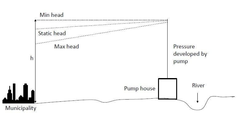
Pumping distribution system without storage
3) Pumping systems with storage (dual system)
This is a combination of gravity and pumping system. In this system, excess water during periods of low consumption is stored in elevated tanks. At the time of high consumption, stored water in elevated tanks augments pumping and peak demand is fulfilled.
Pumps do not have to be run at varying speeds, thus reducing wear of pumps.
This method is more reliable and economical. Stored water in elevated tanks fulfills water requirements during breakdown pumps and for fire fighting.
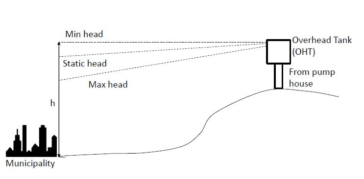
Dual distribution system
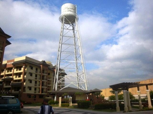
Overhead tank
Different layouts of distribution systems
There are six methods of laying distribution pipes in a locality of colony:
- Dead end or tree system
- Grid-iron system
- Circular or ring system and
- Radial system
- Continuous System
- Intermittent System
Each system has its own advantages and disadvantages and no locality can adopt only one of these systems.
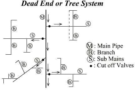
1) Dead end or Tree system
It consists of one supply or trunk main, from which submains are taken. Branches are taken from submains and lastly service connections are given to consumers from these branches.
Diameter of mains, submains and branches are all suitably designed according to the population they serve. This layout can be adopted for cities which have developed in a very haphazard manner.
In this system, main lines run along the main roads of the city. Submains run along the roads originating from the main roads and on both sides of the roads. Branch lines run along streets and are connected to submains. From the branches services connections are given to individual houses.
Dead end or Tree system – Advantages
- It is possible to calculate accurately, the discharge and pressure at any point in the distribution system. Calculations are simple and easy to do.
- This system requires comparatively less number of cut-off valves and hence proves cheaper.
- Diameter of mains are to be designed for the population they have to serve. This fact makes the system cheap and economical. In other layout methods, at any point, water comes from multiple pipes. Thus, calculations for pipe diameter become complex.
Dead end or Tree system – Disadvantages
- During breakdown and maintenance, large areas which are served by pipes, go dry.
- There are large number of dead ends, where water does not circulate but remains static, which may cause contamination. This may endanger public life.
- As a remedy to this problem, scour valves are provided at dead ends and stagnant water is drained out periodically by opening these valves. This implies wastage of large amounts of water.
- Water available for firefighting will be limited, since it is being supplied for only one water main.
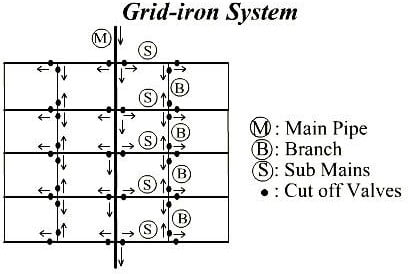
2) Grid iron system
This system is also sometimes called rectangulation or interlaced system. It is a modified form of dead end system. All the dead ends of the mains, submains and branches are interconnected with each other.
Like dead end, main lines are laid along main roads and streets. From submains and mains, branches are taken out and interconnected.
This system of layout is more suitable for cities with well-planned roads and streets. However, this method can be adopted for irregularly developed cities too.
Dead end or branched system vs. grid iron/looped system

Grid iron system – Advantages
- At the time of breakdown or repairs, only small portion of distribution layout is affected.
- As there are no dead ends and free water circulation is achieved throughout, it is not liable to contamination.
- Water reaches all points with minimum loss of head.
- At the time of fires, plenty of water may be diverted and concentrated for fire fighting by manipulating cutoff valves.
Grid iron system – Disadvantages
- Cost of piping is greater because more pipe length is required.
- It is difficult to calculate pressures and discharges at various points of distribution system.
- More number of valves are required.
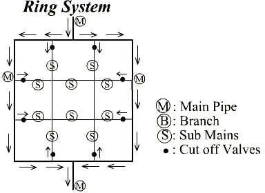
3) Circular or Ring system
This system of layout can be adopted only in case of well-planned colonies. In this system, each locality is divided into square blocks or circular blocks and water mains are laid out around its boundary. Submains and branches are laid along inner roads.
Every point receives its supply from two directions. This system is best of all but requires large number of valves and pipes. Designing the system is easier.
4) Radial system
This system of layout is the reverse of ring system. In this system, water is taken from mains and pumped through the distribution reservoirs which are situated at centers of different zones. Water is supplied through radially laid pipelines.
This method of water supply gives quick service and calculations for design of
pipe sizes are simple.
This method is most suitable for cities with radially spread out roads.

Methods of water supply
Water can be supplied to the consumers by the following two systems:
Continuous system intermittent system
5) Continuous system
Water is supplied to consumer continuously for 24 hours a day. It is the most ideal system and as far as possible, should be adopted. But this system is possible only when there is sufficient quantity of water available from the source. Adequate quantities are available for fire fighting. Also, due to continuous circulation, water remains fresh.
Disadvantage of this method is that water is wasted if end users do not possess civic sense.
Advantages
- Consumers do not have to store water.
- Adequate quantities of water remain available for fire-fighting.
- Wastage of water is less.
This point is debatable. Some say that wastage is more in intermittent systems because consumers leave their taps open during non-supply hours. It is possible that water may not be required but remains flowing causing lot of wastage.
Old water may be thrown out to waste and changed with fresh water in storage tanks.
6) Intermittent system
Water is supplied to consumers only during fixed hour continuously for 24 hours a day. It is the most ideal system and as far as possible, should be adopted. But this system is possible only when there is sufficient quantity of water available from the source. Adequate quantities are available for fire fighting. Also, due to continuous circulation, water remains fresh.
Advantages
- This system is suitable when source water is limited in amount.
- Since people make storage tanks at home, it is possible for them to pull on from stored water for a day or two during emergencies.
Disadvantages
- Disadvantage of this method is that water is wasted if end users do not possess civic sense.
- Consumers have to store water for non-supply hours. This water may not maintain the same degree of purity till used.
- People have to construct storage tanks at their homes, which adds to cost of the scheme.
- Bigger sized pipes have to be laid because full day supply has to be provided within few hours.
- During hours of non-supply, pressure in mains falls below atmospheric pressure. Hence, VOCs and soil particles (PM) may be sucked in through pipes and valves etc.
- If sewer line passes by the side of water pipe, it may cause contamination of water.
- During non-supply hours, consumers may leave their taps open which may cause water wastage.
- During fire incident, it is possible that water may not be available at the fire hydrant. Huge damage may be caused before supply could be turned on.
Pressure in distribution system
The pressure in the distribution system mains should be such that water may reach consumers located at the remotest spots of the locality, with adequate pressure. The pressure in distribution system depends upon factors listed below:
- Pressure required for fire hydrants
- Height of highest building where water has to reach
- Distance of locality from distribution reservoir
Pressure in distribution pipes
Following pressures are considered satisfactory in case of multi-storeyed buildings:
| Upto 3 storeys | 2.1 kg/cm2 |
| 3 to 6 storeys | 2.1 to 4.2 kg/cm2 |
| 6 to 10 storeys | 4.2 to 5.27 kg/cm2 |
| Above 10 storeys | 5.27 to 7 kg/cm2 |
| Commercial districts | 5 kg/cm2 |
| One-storey only | 7 m head |
| Two-storey building | 12 m head |
| Three-storey building | 17 m head |
Pressure for fire hydrants
- Usually a pressure of 5 kg/cm2 at the fire nozzle is recommended, where more than 10 buildings exceed three storeys in height. In low risk areas, 4 kg/cm2 is recommended.
- In sparsely populated areas, 3.5 kg/cm2 is recommended.
- Where fire engines are used, a pressure of 1.5 kg/cm2 is considered satisfactory.
Factors For Pressure in distribution system
While designing distribution system pipes, following points should be kept in mind:
- The main line should be designed to carry 3 times the average demand of city.
- Service pipe should be able to carry twice the average demand.
- Water demand at various points on the line should be carefully computed.
- Length and size of each pipe should be clearly marked on the site plan along with positions of hydrants, valves, meters etc.
- The drop pressure at the end of each pipe line should be calculated and marked.
Velocity in distribution Pipes
The minimum velocity of flow in the pipe should not be less than 0.6 m/s. For best results, the velocities of different pipes should be as follows:
| Pipe diameter (cm) | Velocity (m/s) |
| 10 | 0.9 |
| 15 | 1.2 |
| 25 | 1.52 |
| 40 | 1.82 |
Design of distribution system
Once velocity of flow is established, loss of head due to friction and bends may be calculated. Head required to develop a particular velocity in a particular sized pipe is calculated.
Pipe hydraulics
Following formulae can be used to calculate head losses:

Value of K1 for bends are given as follows. These values are taken from Babbit and Doland.
| 0.2 | 0.4 | 0.6 | 0.8 | 1.0 | 1.2 | 1.4 | 1.6 | 1.8 | 2.0 | |
| K1 | 0.13 | 0.14 | 0.16 | 0.21 | 0.29 | 0.44 | 0.66 | 0.98 | 1.40 | 1.98 |
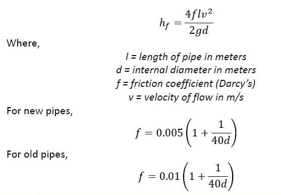
Friction loss in pipes (Darcy Weisbach formula)


![]()
Flow in pipes (Hazen William’s Formula)
The procedure for design discussed in previous discussion becomes very tedious. Also, in water distribution systems, pipes are usually interconnected, which makes calculations for pressure even more complex.
Hazen Williams’ nomograms are universally used in design of water distribution pipes.
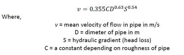
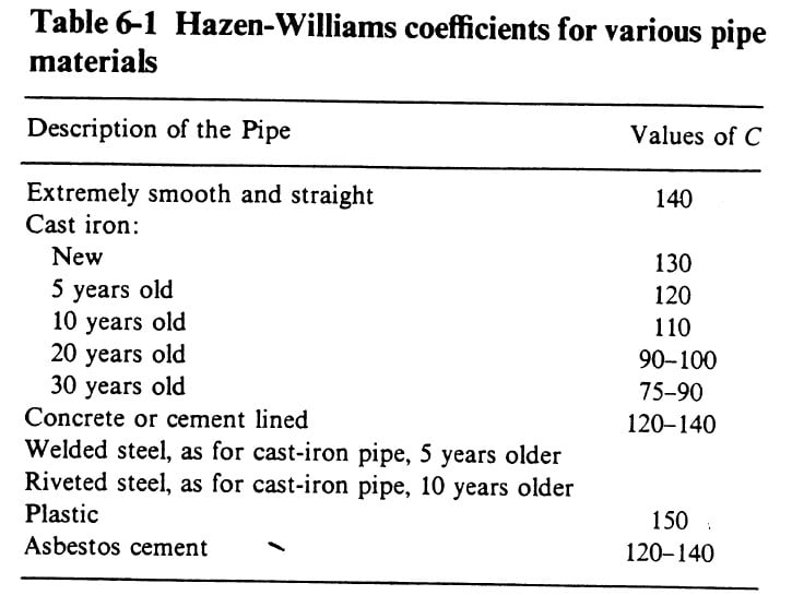 Table contains values of C.
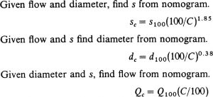
Hazen William formula is very complex and not easily solvable. To ease the task of calculations, nomograms such as the one shown here have been developed:
The nomogram is based upon the value of C as 100 and will apply to pipes which have been in use for at least 15 to 20 years. The nomogram sets up relation between discharge, diameter of pipe, head loss due to friction and velocity of flow. If any two elements are known, the remaining two may be read from the nomogram. Put a straight edge at other two vertical columns and read the unknown values.
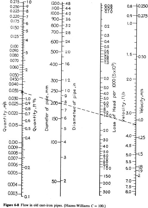
Nomogram is based upon value of C = 100. To determine loss of head, diameter and discharge at any other value of C, use the following equations
Procedure for analyzing pipe size and pressure
- Detailed maps are prepared for the whole area to be supplied with water. Normally, the whole area is subdivided into smaller districts/blocks. All districts are thoroughly surveyed and mapped. All streets, parks, gardens, houses, blocks, apartments etc. should be clearly marked on map.
- The layout of pipes is then marked along the main roads and streets. Direction of flow should be clearly marked.
- Water requirements should then be determined by counting population to be served and other civic requirements on each block length of pipe. Block length of pipe is generally taken as length between two adjacent junctions. By knowing population concentration on each block length of pipe and quantity of water required by population, quantity of water to be supplied through each block can be calculated.
- Now start analyzing the system. Analysis is started from tail end and carried out towards distribution reservoir. Total quantity of water to be carried by each section is then found on cumulative basis.
- This gives the average flow to be carried by pipes. The peak flow for which network is usually designed is 1.8 to 3 times the average flow.
- Now the pipe sizes are assumed in such a way that the velocity of flow in pipes may lie between 0.6 m/s to 1.0 m/s.
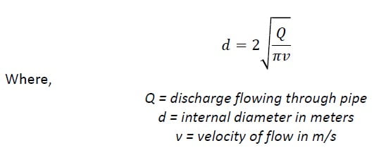
- Now knowing pipe diameter, velocity of flow and lengths, head loss due to friction in each length of pipe is found using formula:
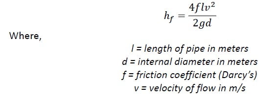
The head loss due to friction can also be found using Hazen William nomogram.
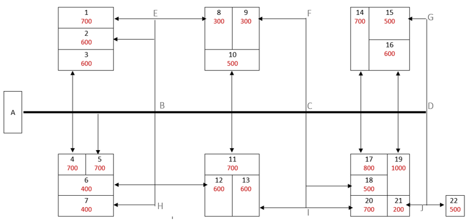
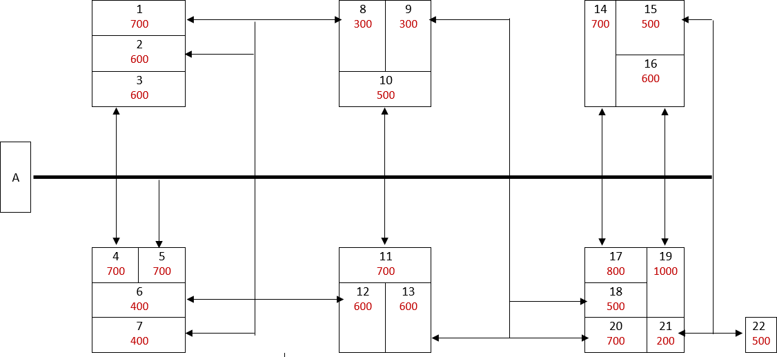
Practical Example
A typical layout of pipes in dead end pattern is given in figure below. The rate of supply per head is 180 LPCD and the populations in different residential blocks of houses is given in the figure (red). The ground elevation of the bottom of the elevated storage tank A is 150 m. Elevations of points A, B, C and D are 130, 129, 131 and 128 m respectively.
Design suitable size of pipes. AB, BC and CD lengths are 300, 400 and 500 respectively.

| Blocks | Population served | |
| PREVIOUS | ||
| From point D | 15,21,22 | 1200 |
| From point C | 9,13,14,15,16,17,18,19,20,21,22 | 6400 |
| from point B | 1,2,6,7,8,9,10,11,12,13,14,15,16,17,18,19,20,21,22 | 10600 |
| From point A | 1,2,3,4,5,6,7,8,9,10,11,12,13,14,15,16,17,18,19,20,21,22 | 12600 |
| LOCAL | ||
| Between C and D | 14.16.17,19 | 3100 |
| Between B and C | 10,11 | 1200 |
| Between A and B | 3,4,5 | 2000 |