Table of Contents
Base Line Measurement Method
In surveying procedures such as traversing, triangulation, trilateration, and setting out, baseline measurement is very important. The base line is the most critical line in triangulation and is measured very precisely.
This is due to the fact that the accuracy of triangulation is determined on the accuracy of the triangle sides derived from the base line.
The base line measurement, in addition to being a complement to angle measurement in triangulation, can also be used to define the scale of triangulation.
What is Baseline ?
The line on which the framework of the survey is built is known as the base line. The base line is the most essential line of the survey, and it is usually the longest of the main survey lines and lies fairly in the middle of the ground contributing to triangles as a reference line. This line should be drawn on very level ground and measured very carefully and precisely.
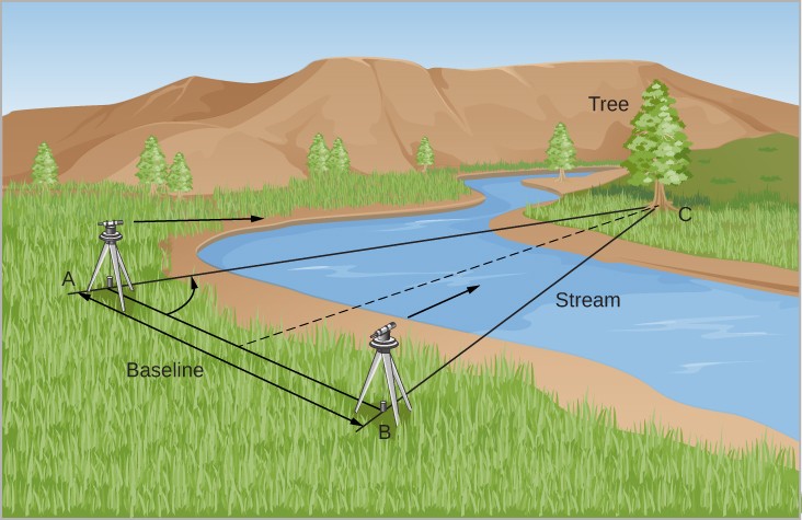
What is Triangulation?
Triangulation is nothing but the system consists of a lot of interconnected triangles in this method, knowing the length of one side and three angles, the length of other two sides of each triangle can be computed.
Selection of Baseline Site
The following points should be remembered during the selection of base line site:
- The location is chosen in such a way that the main surveying principle is strictly followed.
- The station points on site is inter visible.
- The terrain is somewhat flat, consistently sloped, or softly undulating.
- The site is selected that well-conditioned triangles is formed.
- The longest of the main survey lines is the base line.
- The main survey lines run near the boundary line of the area surveyed.
How to measure Baseline
In surveying procedures such as traversing, triangulation, trilateration, and setting out, baseline measurement is critical. Prior to the invention of the Electromagnetic Distance Measuring Instrument, baseline measurements were made with equipment such as tapes, chains, and bands (EDM).
The method of measuring baseline with early instruments has largely been replaced by distance measurements using electromagnetic means. So, basically there are two methods to measure the base line.
1)Conventional method
- Wheeler’s method
- Jadrein’s method
2)Electronic Distance Measurement
1). Conventional Method:

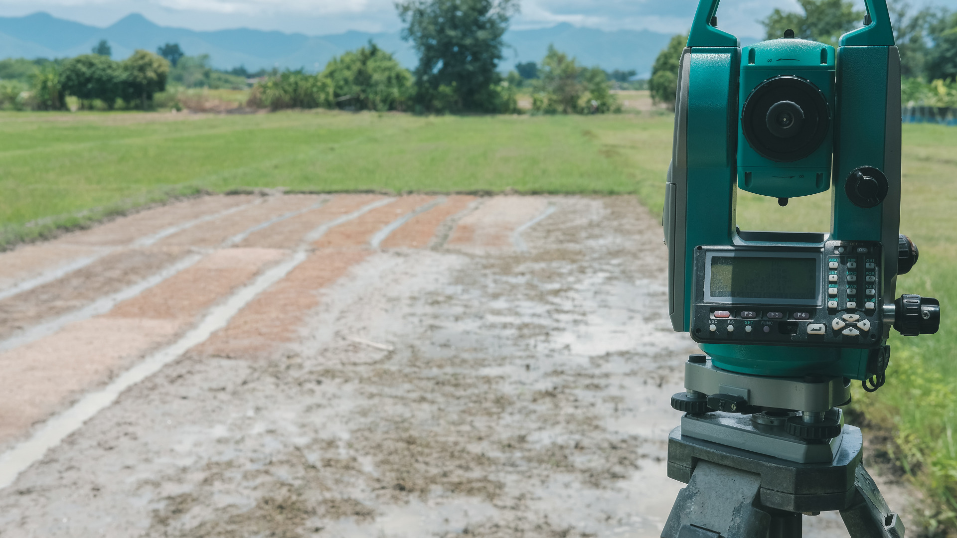
Theodolite
To use these methods, first field work is executed by two groups of surveyors. One is called setting out group consists of two surveyors and several porters, is responsible for aligning the measuring tripods prior to the measurement and at the proper intervals and the second group is called the measuring party, consisting of two observers, leveler, recorder and staff man, for actual measurements.
The obstructions are removed from the base line, which is then split into reasonable segments of up to one kilometer in length and is accurately aligned using theodolite.
Stout posts or marking stakes are driven firmly into the ground whenever the alignment changes. The setting out party then aligns the measuring tripods in preparation for the measurement, which can be accomplished in two ways:
- Measurement on Wheeler’s method by Wheeler’s base line apparatus.
- Jaderin’s method.
i) Wheeler’s Method:
In this method the marking stakes are driven into the ground at regular intervals (less than the length of one tape) on the base line in such a way that their tops are 50 cm above the ground.


- A 4 cm wide zinc strip is nailed on these marking stakes in order to avoid extremities of tape.
- Between these marking stakes, supporting stakes are also placed at interval of 5 to 15 meters with their faces in the line.
- The level of these supporting marking stakes must be same or on uniform grade (increasing or decreasing by constant level).
- As shown in figure, straining rods are placed. One end of tape (forward end) is attached to the weight by pulley of straining rod from where pull is applied and other end of tape is attached with spring balance at the other straining rod in order to measure this tension created by this pull.
- After this the tape at forward stake and at rear stake is adjusted to coincide with the mark on zinc strips (center of marking stake).
- The position of these coinciding points is noted and distance between these marks is measured. Temperature is noted at each marking and work continues to the next marking stake.

ii) Jaderin’s Method:
In this method, instead of straining poles, trestles (straining tripods) are used and measuring tripods are used in place of marking stakes.
- There are two points taken.
- Position the theodolite on one station and the ranging rod on the other.
- Between the two measuring sites, place two or three tripod stands. These tripods are placed at regular intervals.
- All the tripods are aligned (ranged) along the line.
- After aligning these tripods, ranging rod and theodolite are also replaced with tripods.
- Another theodolite is placed in the vicinity of field to check whether all the tripod stands are at same level or not. If not, then first level the tripods to proceed next.
- One end of tape is pulled by applying load and other end is attached with spring balance to measure this pull (as in wheeler’s method).
- At each stage, the temperature is recorded for temperature correction.
- Tension (pull) is created in the tape during length measurement, which is measured by the spring balance. The pull should not be more than 20 times of the weight of tape. The procedure is repeated till all base line is covered.

Corrections:
Jaderin introduced some corrections for more accurate measurements. These are as follow:
Corrections in Taping:
- When the uncorrected length must be extended in order to reach the true length, the correction is said to be plus or positive.
- When the uncorrected length must be reduced in order to reach the true length, the correction is said to be negative.
i)Correction for Absolute Length
Absolute length = Nominal Length ± Ca
Ca = L (l’ – l)/L
where:
L = Measured or Recorded Length
l = Nominal Length of a tape
l’ = Actual Length of a tape
Ca = Correction for Absolute Length
The sign of the correction is determined by l and l’ values. However, because l’ is typically more than l, this adjustment is usually positive, indicating that when a tape is stretched and is too long, it reads too short.
ii)Correction for Temperature
Ct = α(Tm-To)L
Where:
α = Coefficient of Thermal Expansion
Tm = Mean Temperature during Measurement
To = Temperature of calibration Measured Length
iii)Correction for Pull/Tension
Cp = (P – Po)L/AE
Where
P = Pull applied during
Po = Pull under which the tape was calibrated
L = Measured Length
A = Cross sectional Area of the tape
E = Modulus of Elasticity of Tape Material
iv)Correction for Sag:
Cs = w2 L3 cos2φ/(24P²)
where
P = Pull applied during measurement
φ = Angle of slope between tape supports
w = Weight of tape per unit length
W = Total Weight of Tape
v)Correction for Slope
C = L (1 – cosφ )
OR
C = L – √(L² – h²)
C = h²/(2 L)

All these corrections are applied to the measured length in order to get accurate results.
2). Electronic Distance Measurement

EDM total station
Only in the early 1950s the first electronic distance measuring equipment were developed. These primarily consisted of Electro-optical and electromagnetic instruments. They were bulky heavy and expensive. The typical EDM today uses the Electro-optical principle. They are small reasonably lightweight highly accurate but still expensive.
The use of EDM technology removes the requirement for extensive baseline preparation. The use of EDM greatly simplifies the baseline measurement process. Since 1950, baseline measurement using invar wires has been replaced by a far more convenient form of measurement, namely the use of Electro Magnetic Distance Measurement (EDM).
EDM reduces the requirement for time-consuming baseline preparations. The length of the baseline has no bearing on the time it takes to take the requisite instrument reading during the actual measuring procedure.
Methodology
1)Determination of EDM zero correction:
The approach for determining the zero correction of an EDM was to divide a long straight line into parts. The approach for determining the zero correction of an EDM is to divide a long straight line into parts. The appropriate sections were measured, as well as the long line, and the zero correction was computed.
2)Setting out of base line:
A theodolite and ranging poles are used to set out the baseline. set up the theodolite on the starting point after a pillar has been placed. The direction is defined by pointing the theodolite in the predetermined direction. place the beacons at the two ends of the baselines.
Use the EDM work in conjunction with theodolite and the battery fixed. It has to be then set over pillar and level the reflector too. After that, the following operation should be carried out
The height of EDM instrument and reflector’s height are measured with line tape and record in the field book. The intension is to determine the slope correction to bring the measured slope distance to horizontal distance.
Reflector is then sighted, the prism’s center is bisected, and the theodolite’s vertical and horizontal movement is clamped. Checks for a battery and turns on the instrument’s on/off switch to make the signal.
The display reads 0000, which means the instrument is ready to use. The “MEASURE” knob is softly touched to start the measurement. The distance measurement is completed automatically in less than 5 seconds, during which time points on the digital display flash and the measured distance is displayed.
- For slope correction, the theodolite’s vertical angle reading is recorded.
- The temperature of the atmosphere is also taken into account.
3)EDM Measurement:
- To measure any distance, you simply compare it to a known or calibrated distance for example by using a scale or tape to measure the length of an object in EDM’s the same comparison principle is used the calibrated distance in this case is the wavelength of the modulation on a carrier wave.
- Modern EDM’s use the precision of a quartz crystal oscillator and the measurement of phase shift to determine the distance.
- The EDM is set up at one end of the distance to be measured and a reflector at the other end.
- The EDM generates an infrared continuous wave carrier beam which is modulated by an electronic shutter.
- This beam is then transmitted through the aiming optics to the reflector.
- The reflector returns the beam to the receiving optics where the incoming light is converted to an electrical signal allowing a phase comparison between transmitted and received signals.
- The amount by which the transmitted and received wavelengths are out of phase can be measured electronically and registered on a meter to within a millimeter or two.
The advent of EDM equipment has completely revolutionaries all surveying procedures and resulted in a change of emphasis and techniques, by reason of the fact that distance can now be measured quickly and accurately, regardless of terrain condition.