Table of Contents
What Is Cross Drainage Works?
IRRIGATION STRUCTURES – 2
In an irrigation project, when the network of main canals, branch canals, distributaries, etc. are provided, then these canals may have to cross the natural drainages like rivers, streams, nallahs, etc at different points within the command area of the project. The crossing of the canals with such obstacle cannot be avoided. So, suitable structures must be constructed at the crossing point for the easy flow of water of the canal and drainage in the respective directions. These structures are known as cross-drainage works.
Necessity of Cross-drainage works:
- The water-shed canals do not cross natural drainages. But in actual orientation of the canal network, this ideal condition may not be available and the obstacles like natural drainages may be present across the canal. So, the cross drainage works must be provided for running the irrigation system.
- At the crossing point, the water of the canal and the drainage get intermixed. So, far the smooth running of the canal with its design discharge the cross drainage works are required.
- The site condition of the crossing point may be such that without any suitable structure, the water of the canal and drainage can not be diverted to their natural directions. So, the cross drainage works must be provided to maintain their natural direction of flow.
Types of Cross-Drainage Works:
- Type I (Irrigation canal passes over the drainage)
- Aqueduct
- Siphon aqueduct
- Type II (Drainage passes over the irrigation canal)
- Super passage
- Siphon super passage
- Type III (Drainage and canal intersection each other of the same level)
- Level Crossing
- Inlet and outlet
Selection of type of cross-drainage works
- Relative bed levels
- Availability of suitable foundation
- Economical consideration
- Discharge of the drainage
- Construction problems
Aqueduct
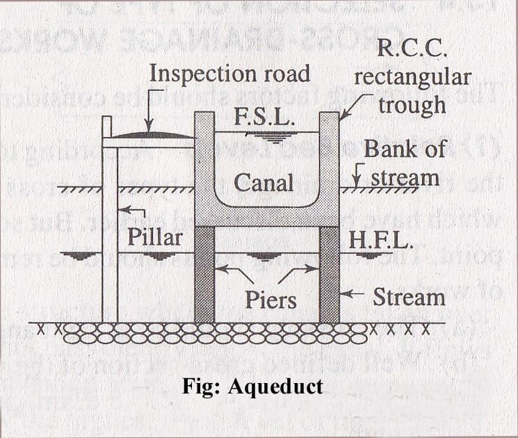
The aqueduct is just like a bridge where a canal is taken over the deck supported by piers instead of a road or railway. Generally, the canal is in the shape of a rectangular trough which is constructed with reinforced cement concrete. Sometimes, the trough may be of trapezoidal section.
- An inspection road is provided along the side of the trough.
- The bed and banks of the drainage below the trough is protected by boulder pitching with cement grouting.
- The section of the trough is designed according to the full supply discharge of the canal.
- A free board of about 0.50 m should be provided.
- The height and section of piers are designed according to the highest flood level and velocity of flow of the drainage.
- The piers may be of brick masonry, stone masonry or reinforced cement concrete.
- Deep foundation (like well foundation) is not necessary for the piers. The concrete foundation may be done by providing the depth of foundation according to the availability of hard soil.
Siphon Aqueduct
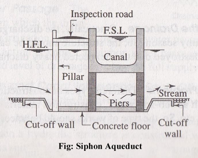
The siphon aqueduct, the bed of the drainage is depressed below the bottom level of the canal trough by providing sloping apron on both sides of the crossing.
- The sloping apron may be constructed by stone pitching or cement concrete.
- The section of the drainage below the canal trough is constructed with cement concrete in the form of tunnel. This tunnel acts as a siphon.
- Cut off walls are provided on both sides of the apron to prevent scouring.
- Boulder pitching should be provided on the upstream and downstream of the cut-off walls.
- The other components like canal trough, piers, inspection road, etc. should be designed according to the methods adopted in case of aqueduct.
Super Passage
The super passage is just opposite of the aqueduct. In this case, the bed level of the drainage is above the fully supply level of the canal. The drainage is taken through a rectangular or trapezoidal trough of channel which is constructed on the deck supported by piers.
- The section of the drainage trough depends on the high flood discharge.
- A free board of about 1.5 m should be provided for safety.
- The trough should be constructed of reinforced cement concrete.
- The bed and banks of the canal below the drainage trough should be protected by boulder pitching or lining with concrete slabs.
- The foundation of the piers will be same as in the case of aqueduct.
Siphon Super Passage
It is just opposite siphon aqueduct. In this case, the canal passes below the drainage trough. The section of the trough is designed according to high flood discharge. The bed of the canal is depressed below the bottom level of the drainage trough by providing sloping apron on both sides of the crossing.
- The sloping apron may be constructed with stone pitching or concrete slabs.
- The section of the canal below the trough is constructed with cement concrete in the form of tunnel which acts as siphon.
- Cut-off walls are provided on upstream and downstream side of sloping apron.
- Other components are same as in the case of siphon aqueduct.
Level Crossing
The level crossing is an arrangement provided to regulate the flow of water through the drainage and the canal when they cross each other approximately at the same bed level. The level crossing consists of the following components:
- Crest Wall: It is provided across the drainage just at the upstream side of the crossing point. The top level of the crest wall is kept at the full supply level of the canal.
- Drainage Regulator: It is provided across the drainage just at the downstream side of the crossing point. The regulator consists of adjustable shutters at different tiers.
- Canal Regulator: It is provided across the canal just at the downstream side of the crossing point. This regulator also consists of adjustable shutters at different tiers.
River
River Canal Regulator Regulator
Fig: Level Crossing
Inlet and outlet
In the crossing of small drainage with small channel no hydraulic structure is constructed. Simple openings are provided for the flow of water in their respective directions. This arrangement is known as inlet and outlet.
- In this system, an inlet is provided in the channel bank simply by open cut and the drainage water is allowed to join the channel
- At the points of inlet and outlet, the bed and banks of the drainage are protected by stone pitching.
What is Canal Fall?
Irrigation canals are constructed with some permissible bed slopes so that there is no silting or scouring in the canal bed. But it is not always possible to run the canal at the desired bed slope throughout the alignment due to the fluctuating nature of the country slope. Generally, the slope of the natural ground surface is not uniform throughout the alignment. Sometimes, the ground surface may be steep and sometimes it ma be very irregular with abrupt change of grade. In such cases, a vertical drop is provided to step down the canal bed and then it is continued with permissible slope until another step down is necessary. This is done to avoid unnecessary huge earth work in filling. Such vertical drops are known as canal falls or simply falls.
Necessity of Canal Falls:
- When the slope of the ground suddenly changes to steeper slope, the permissible bed slope can not be maintained. It requires excessive earthwork in filling to maintain the slope. In such a case falls are provided to avoid excessive earth work in filling
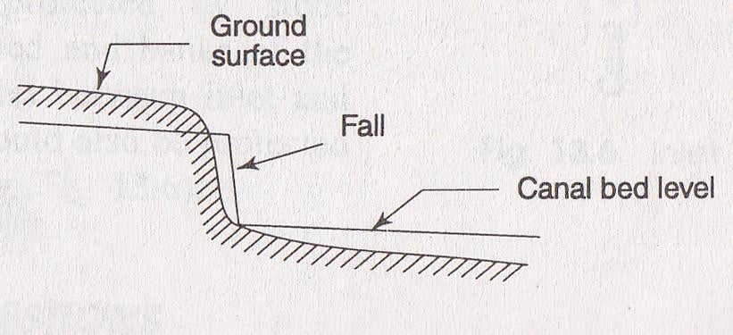
- When the slope of the ground is more or less uniform and the slope is greater than the permissible bed slope of canal. In that case also the canal falls are necessary.
- In cross-drainage works, when the difference between bed level of canal and that of drainage is small or when the F.S.L of the canal is above the bed level of drainage then the canal fall is necessary to carry the canal water below the stream or drainage.
Types of Canal Falls
The following are the different types of canal falls that may be adopted according to the site condition:
Ogee Fall
In this type of fall, an ogee curve (a combination of convex curve and concave curve) is provided for carrying the canal water from higher level to lower level. This fall is recommended when the natural ground surface suddenly changes to a steeper slope along the alignment of the canal.
- The fall consists of a concrete vertical wall and concrete bed.
- Over the concrete bed the rubble masonry is provided in the shape of ogee curve.
- The surface of the masonry is finished with rich cement mortar (1:3).
- The upstream and downstream side of the fall is protected by stone pitching with cement grouting.
- The design consideration of the ogee fall depends on the site condition.
Rapid Fall
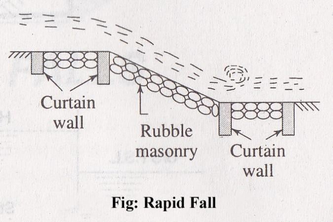
The rapid fall is suitable when the slope of the natural ground surface is even and long. It consists of a long sloping glacis with longitudinal slope which varies from 1 in 10 to 1 in 20.
- Curtain walls are provided on the upstream and downstream side of the sloping glacis.
- The sloping bed is provided with rubble masonry.
- The upstream and downstream side of the fall is also protected by rubble masonry.
- The masonry surface is finished with rich cement mortar (1: 3).
Stepped Fall
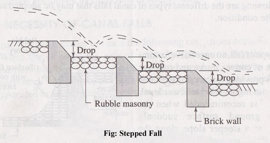
Stepped fall consists of a series of vertical drops in the form of steps. This fall is suitable in places where the sloping ground is very long and requires long glacis to connect the higher bed level with lower bed level.
- This fall is practically a modification of the rapid fall.
- The sloping glacis is divided into a number of drops so that the flowing water may not cause any damage to the canal bed. Brick walls are provided at each of the drops.
- The bed of the canal within the fall is protected by rubble masonry with surface finishing by rich cement mortar (1:3).
Trapezoidal Notch Fall
In this type of fall a body wall is constructed across the canal. The body wall consists of several trapezoidal notches between the side piers and the intermediate pier or piers. The sills of the notches are kept at the upstream bed level of the canal.
- The body wall is constructed with masonry or concrete.
- An impervious floor is provided to resist the scoring effect of the falling water.
- The upstream and downstream side of the fall is protected by stone pitching finished by cement grouting.
- The size and number of notches depends upon the full supply discharge of the canal.
Vertical Drop Fall
It consists of a vertical drop walls which is constructed with masonry work. The water flows over the crest of the wall. A water eastern is provided on the downstream side which acts as a water cushion to dissipate the energy of falling water.
- A concrete floor is provided on the downstream side to control the scouring effect of the flowing water.
- Curtain walls are provided on the upstream and downstream side.
- Stone pitching with cement grouting is provided on the upstream and downstream side of the fall to protect it from scouring.
Glacis Fall
It consists of a straight sloping glacis provided with a crest. A water cushion is provided on the downstream side to dissipate the energy of flowing water.
- The sloping glacis is constructed with cement concrete.
- Curtain walls and toe walls are provided on the upstream and downstream side.
- The space between the toe walls and curtain walls is protected by stone pitching.
- This type of fall is suitable for drops up to 1.5 m.
For the improvement in energy dissipation, the glacis falls have been modified as follows:
Montague Type Fall
In this type of fall, the straight sloping glacis is modified by giving parabolic shape which is known as Montague profile. Taking “0” as the origin, the Montague profile is given by the equation,
Where, x = distance of point P from OX axis, Y = distance of point P from OY axis, υ = velocity of water at the crest,
The main body of the fall is constructed with cement concrete. Toe walls and curtain walls are same as in the case of straight sloping glacis. The bed protection by stone pitching is also same.
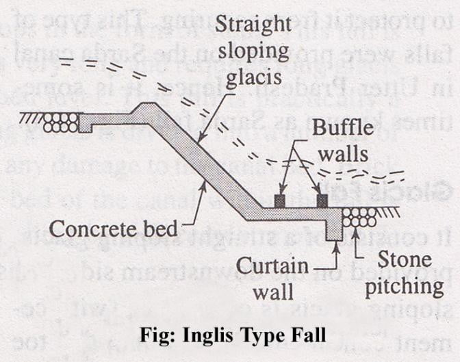
Inglis Type Fall
In this type of fall, the gracis is straight and sloping, but buffle walls are provided on the downstream floor to dissipate the energy of flowing water.
-
- The height of buffle depends on the head of water on the upstream side.
- The main body of the fall is constructed with cement concrete.
- The toe walls and curtain walls are same as straight glacis.
- The protection works with stone pitching are also same. Sometimes, this fall is known as buffle fall.
Canal Regulators:
Fig: Canal Regulators
A head regulator provided at the head of the off-taking channel, controls the flow of water entering the new channel.
While a cross regulator may be required in the main channel downstream of the off-taking channel, and is operated when necessary so as to head up water on its upstream side, thus to ensure the required supply in the off-taking channel even during the periods of low flow in the main channel.
Main functions of a head regulator:
- To regulate or control the supplies entering the off-taking canal
- To control the entry of silt into the off-taking canal
- To serve as a meter for measuring discharge.
Main functions of a cross regulator:
- To control the entire Canal Irrigation System.
- To help in heading up water on the upstream side and to fed the off-taking canals to their full demand.
- To help in absorbing fluctuations in various sections of the canal system, and in preventing the possibilities of breaches in the tail reaches.
- Cross regulator is often combined with bridges and falls, if required.
Typical Layout and Cross-section of a regulator:
| Abutment | H E A D
W A L L |
H E A D
W A L L |
Abutment | |
| Vent – 1 | ||||
| Pier | Pier | |||
| Vent – 2 | ||||
| Pier | Pier | |||
| Vent – 3 | ||||
| Abutment | Abutment |


