Table of Contents
Traversing
A geometrical figure, consisting of a series of consecutive survey lines is called traverse. Points joining these lines are called traverse points. Traverse consists of angle and distances.
Traversing is the approach of control survey (Control Surveys are used to create long-term, sustainable reference points that can be utilized as the foundation for and throughout the lifecycle of a project) to establish control points (reference points). It includes linear and angular measurement.
Get all your industrial equipment from Ejawda
Purposes
It is a quick and easy way to establish horizontal control especially when the lines of sight are short owing to heavily built-up areas and unable to apply triangulation and trilateration. Following are the purposes of traversing
- Surveys of properties to locate or establish boundaries
- For topographic mapping surveys by using supplementary horizontal control
- Location and construction layout surveys
- Photogrammetric mapping using ground control survey
Types of traverses
There are two types of traverses according to the arrangement of traverse lines i.e. Open traverse and close traverse.
Open traverse:
An open traverse is a traverse in which its lines are so arranged that last traverse point does not meet with the first traverse point. It is also called unclosed traverse.
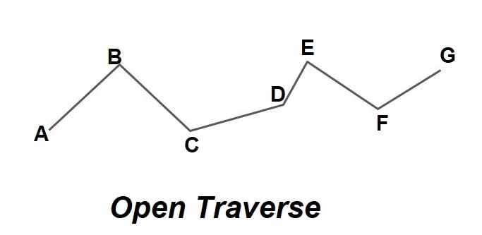
Figure 1: Open traverse
Open traverses can be used for prolonged distances but lacking the ability to double-check the accuracy of the work in progress. Consequently, all survey measurements are meticulously repeated during the time of work, and if there is any chance for verifying position and direction, advantage of it is taken. E.g.
- When a project is in progress, flanking property surveys and interconnecting road and railroad rights-of-way are checked.
- Surveying techniques based on the global positioning system (GPS) are also used to evaluate and authenticate traverse station positioning.
This type of traverse survey is suitable for roads, canals, rail tracks and sewerages or pipes.
Closed traverse:
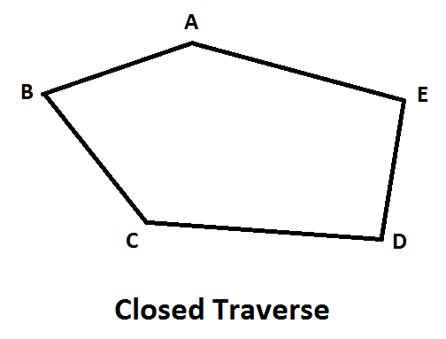
Figure 2: Closed traverse
The traverse in which last traverse point meets the first traverse point forming a close figure is called close traverse. It is also defined as surveying traverse whose correctness may be determined by the fact that the angles should add up to 360 degrees when it is closed (as a close polygon has 360 angle), and which terminates at its starting point.
It’s ideal for determining the boundaries of ponds, sports fields, and forests. Its disadvantage is that when a traverse is close, work done is double as once going and once coming back.
Methods of traversing:
Following are the methods of traversing explained.
1)Chain traversing:
Figure 3: Chains
In this approach chain and tape are used throughout the project. There is no angle measuring tool utilized and the line directions are totally determined by linear measurements. The angle between traverse lines is measured indirectly by using chain angle concept (constructing the third side utilizing tie stations to find the angle between two adjoining sides)
When triangulation is difficult to implement, chain surveying is used. It is not suitable for precise traversing because there are modern methods which offer both linear and angular measurements of the area to be surveyed.
2)Compass traversing:
In this approach, the fore and rear bearings (a bearing is the clockwise or counterclockwise angle between north or south) of the traverse legs are calculated with a prismatic compass, and linear measurement (distances) is done by using chain or tape.
The noted bearings are then double-checked, and any necessary modifications for nearby attractions are made. A closure error may occur in this procedure. Using ‘Bowditch’s rule,’ this error is graphically adjusted.
In this Bowditch’s rule, the angular inaccuracy in a side is distributed proportionally to the length of that side in this manner. Calculate the length or gap of error as €L and then distribute proportionally to the length of the different sides if traverse does not close.
Distribution of error on one side = € L * (length of side/transverse perimeter)

Figure 4: Compass
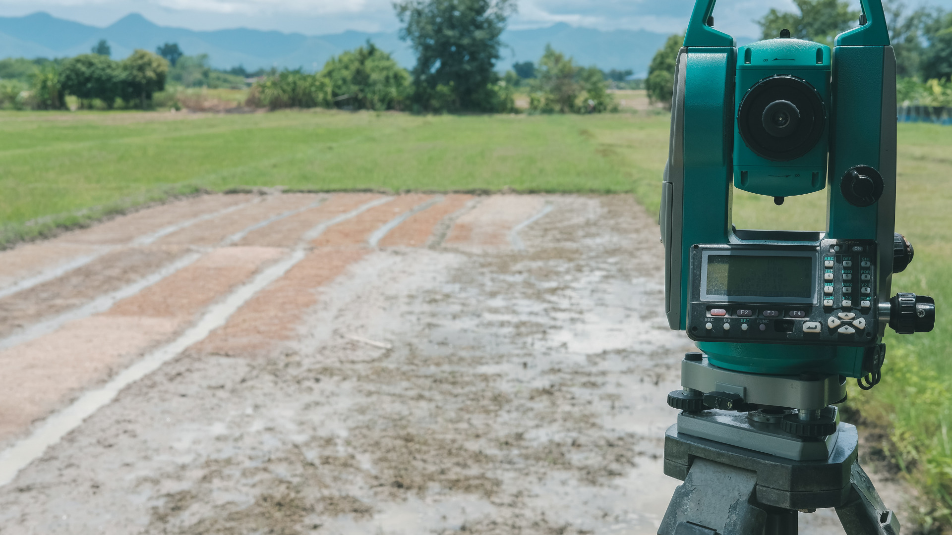
3)Theodolite traversing
With the help of theodolites directions can be measured in the form of the bearings, Deflection angle, Angle to the right, interior angles or azimuths and distance with a tape, electric distance measuring equipment (EDM) or a tachometer in theodolite traversing.
Compass and theodolite can be used to measure bearing using either the lose needle method or the fast needle method.
Traverse is called deflection angle traverse if angles measured by deflection angle method. It is especially employed in urban areas where triangulation is not practicable.
The various purposes for which theodolite can be used are for measuring horizontal angles, vertical angles, deflection angles, magnetic bearings, the horizontal distance between two points, the vertical height of an object. It is also used for ranging a line and finding the difference of elevation between various points.

Figure 5: Theodolite
4)Plane table traversing:
This is like the compass survey in several ways. It is used to trace topographic details by drawing survey lines amid stations that have been formerly places by other survey procedures.
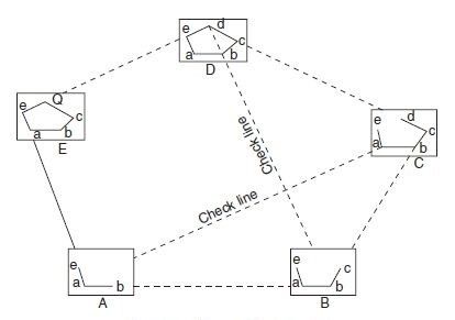
The plane table is placed in a specific location e.g. A. Sight toward B is taken from there, and the distance AB is calculated. The plane table is repositioned at station B and aimed towards A.(this is called back sighting). BA was assessed in terms of distance. On the drawing paper, the average distance between AB and BA is plotted to a suitable scale. The distance was determined after spotting point C from B. This procedure is carried out for each station. Perform some checks at regular intervals
 Figure 6: Plane table traversing